Duet3D Logo Duet3D
    • Tags
    • Documentation
    • Order
    • Register
    • Login
    1. Home
    2. mindbender9
    3. Posts
    • Profile
    • Following 0
    • Followers 0
    • Topics 1
    • Posts 60
    • Best 0
    • Controversial 0
    • Groups 0

    Posts made by mindbender9

    • RE: Beginner Needs Help - Anycubic Kossel Plus + Duet WiFi -- HOW?

      Hi @dc42.

      Yes, I followed the exact directions found in the documentation for "Measuring Trigger Height" here. Yet somehow, I received all sorts of values from measuring the same dead-center spot.

      I'm wondering if my printer is in the Bermuda Triangle.

      I'll change the M558 F value to F200 tonight.

      • Question: In the bed.g, what should the G31 values be? Should the XYZ values be equal to zero or something else (e.g. should they match the G31 line from config.g)?

      Thanks @dc42

      posted in Duet Hardware and wiring
      mindbender9undefined
      mindbender9
    • RE: Beginner Needs Help - Anycubic Kossel Plus + Duet WiFi -- HOW?

      @dc42 said in Beginner Needs Help - Anycubic Kossel Plus + Duet WiFi -- HOW?:

      @mindbender9, please clarify what type of Z-probe you are using. I was assuming it was my own IR sensor, but skimming through this rather long thread, I found user @3mm mentioning the IR sensor but no confirmation that you are using one too.

      Hi @dc42 - The IR sensor that I'm using is the "Mini differential IR height sensor" - I believe this might be one that you designed.

      It is currently mounted on my hot-end with an offset of 32.82mm (distance from the nozzle).

      posted in Duet Hardware and wiring
      mindbender9undefined
      mindbender9
    • RE: Beginner Needs Help - Anycubic Kossel Plus + Duet WiFi -- HOW?

      @dc42 said in Beginner Needs Help - Anycubic Kossel Plus + Duet WiFi -- HOW?:

      1. Is the variance is between probing at different points?

      All points were for the same position. Dead center, at the middle of the bed.

      Inconsistency in the trigger height for the IR sensor can also be due to using a transparent bed surface (e.g. glass or PEI) that is not backed by a black surface, or that has scuff marks on the top.

      Using a replacement black bed top from the manufacturer.

      1. If your initial delta parameters are a long way out, that could cause probe points to be outside the bed limits. Try a smaller probing radius. You can always move some of the probe points further out when you have it working.

      Will do. I’ll reduce the quantity of probe points using the wizard and see what happens.

      Question for @dc42 - What should be entered for G31 in the bed.g file? Should the XYZ values match the config.g G31 line or should they be zeroed out?

      posted in Duet Hardware and wiring
      mindbender9undefined
      mindbender9
    • RE: Beginner Needs Help - Anycubic Kossel Plus + Duet WiFi -- HOW?

      So I performed a number of Trigger Height measurements tonight and only two of the ten tests were even close. I don't understand why there's such a variance between the numbers.

      Z-Height #1: 2.377
      Z-Height #2: 3.953
      Z-Height #3: 2.641
      Z-Height #4: 3.09
      Z-Height #5: 3.391
      Z-Height #6: 4.415
      Z-Height #7: 2.103
      Z-Height #8: 3.628
      Z-Height #9: 3.653
      Z-Height #10: 3.516

      Now, two of the Auto Calibration points land outside of the bed. And I'm unable to change these outside positions no matter what G1 Xx Yy Z99999 H0 values I save to the bed.g file. It's like the board isn't reading the bed.g file. What happened?

      What do I do now?

      posted in Duet Hardware and wiring
      mindbender9undefined
      mindbender9
    • RE: Beginner Needs Help - Anycubic Kossel Plus + Duet WiFi -- HOW?

      @dc42 said in Beginner Needs Help - Anycubic Kossel Plus + Duet WiFi -- HOW?:

      Measure the IR sensor trigger height and use that value in the G31 Z parameter instead.

      • When you say to measure the trigger height for the IR sensor, what height would that be? Is that the Z-position from the bed to the bottom of the sensor? But at what height? I'm don't understand.

      Edit: I'll go over the "Measuring the trigger height" section of your instructions when I get home. Thanks!

      One other question:

      • The G31 line from the bed.g file says:
      G31 X0 Y0 Z20
      

      While the config.g line has:

      G31 X0 Y-32.82 Z0 P500
      

      Question: Should the two G31 lines match in both files?

      Thanks for your help!

      posted in Duet Hardware and wiring
      mindbender9undefined
      mindbender9
    • RE: Beginner Needs Help - Anycubic Kossel Plus + Duet WiFi -- HOW?

      Terrible results when I try to print.

      • Good News: I've taken care of the Z-probe setup. I changed the bed.g file settings to only use three calibration points and it worked. So I went back to the 10-point settings and changed any that went off the bed. When I click Auto-Delta Calibration, all 10 calibration points now complete successfully - the nozzle comes within 0.2mm of the bed, the Z-probe LED flashes and the nozzle retracts then goes to the next point. I have placed the M500 code at the end of bed.g and M501 at the end of config.g.

      • Bad News: Whenever I upload a gcode file of a 0.2mm test circle (after performing a calibration prior), the nozzle buries itself hard into the bed. Every time. And while I am not fast enough to power off the nozzle (it's dropping that fast), I think I'm at my last ropes here. I'm attaching whatever config files I have at this point.

      • More Bad News: The Duet Wifi web interface keeps disconnecting when I open the webpage in either Google Chrome or Microsoft Edge. It takes 30 seconds or more to allow me to reconnect, or I have to manually restart the board.

      • Question: Why does the nozzle bury itself into the bed when I just auto-calibrated the printer a few seconds before? Why is there a height difference that puts the Z-position below the bed after the auto-calibration?

      config.g:

      ; Configuration file for Duet WiFi (firmware version 1.20 or newer)
      ; executed by the firmware on start-up
      ;
      ; generated by RepRapFirmware Configuration Tool on Sun May 13 2018 19:16:40
      
      ; General preferences
      G90					; Send absolute coordinates...
      M83					; ...but relative extruder moves
      M555 P1					; Set firmware compatibility to look like RepRapFirmare
      
      ;*** The homed height is deliberately set too high in the following - you will adjust it during calibration.
      M665 R134 L270 B85 H300		; Set delta radius, diagonal rod length, printable radius and homed height
      M666 X0 Y0 Z0			; Put your endstop adjustments here, or let auto calibration find them
      
      ; Network
      M550 Pduettest
      M552 S1					; Enable network
      M586 P0 S1				; Enable HTTP
      M586 P1 S0				; Disable FTP
      M586 P2 S0				; Disable Telnet
      
      ; Z-Probe 
      M558 P1 X0 Y0 Z0 H30 F1000 T5000 ;I1 		; Set Z probe type to DC42 and the dive height + speeds
      G31 X0 Y-32.82 Z0 P500				; Set Z probe trigger value, offset and trigger height
      M557 R80 S20					; Define mesh grid
      
      ; Drives
      M569 P0 S1					; Drive 0 goes forwards
      M569 P1 S1					; Drive 1 goes forwards
      M569 P2 S1					; Drive 2 goes forwards
      M569 P3 S1					; Drive 3 goes forwards
      M350 X16 Y16 Z16 E16 I1				; Configure microstepping with interpolation
      M92 X80 Y80 Z80 E96				; Set steps per mm
      M566 X1200 Y1200 Z1200 E1200			; Set maximum instantaneous speed changes (mm/min)
      M203 X18000 Y18000 Z18000 E1200			; Set maximum speeds (mm/min)
      M201 X1000 Y1000 Z1000 E1000			; Set accelerations (mm/s^2)
      M906 X1000 Y1000 Z1000 E800 I30			; Set motor currents (mA) and motor idle factor in per cent
      M84 S30						; Set idle timeout
      
      ; Axis Limits
      M208 Z0 S1					; Set minimum Z
      
      ; Endstops
      M574 X2 Y2 Z2 S1				; Set active high endstops
      
      ; Heaters
      M305 P0 T100000 B4267 C0 R4700			; Set thermistor + ADC parameters for heater 0
      M143 H0 S120					; Set temperature limit for heater 0 to 120C
      M305 P1 T100000 B4267 C0 R4700			; Set thermistor + ADC parameters for heater 1
      M143 H1 S275					; Set temperature limit for heater 1 to 275C
      
      ; Fans
      M106 P0 S0.3 I0 F500 H-1 ; Set fan 0 value, PWM signal inversion and frequency. Thermostatic control is turned off
      M106 P1 S1 I0 F500 H1 T45 ; Set fan 1 value, PWM signal inversion and frequency. Thermostatic control is turned on
      M106 P2 S1 I0 F500 H1 T45 ; Set fan 2 value, PWM signal inversion and frequency. Thermostatic control is turned on
      
      ; Tools
      M563 P0 D0 H1					; Define tool 0
      G10 P0 X0 Y0 Z0					; Set tool 0 axis offsets
      G10 P0 R0 S0					; Set initial tool 0 active and standby temperatures to 0C
      
      ; Automatic saving after power loss is not enabled 
      M501
      
      ; Custom settings are not configured
      

      bed.g:

      ; bed.g
      ; called to perform automatic delta calibration via G32
      ;
      ; generated by RepRapFirmware Configuration Tool on Sun May 13 2018
      
      M561 			; clear any bed transform
      G31 X0 Y0 Z20		; POSSIBLE PROBLEM WITH Z=32.82
      ;G31 X0 Y0 Z32.82		; don't want any probe offset for this - ADDED 5/21/2018
      G28			; home the printer
      
      M401			; deploy the Z probe
      
      ; bed.g file for RepRapFirmware, generated by Escher3D calculator
      ; 10 points, 6 factors, probing radius: 105, probe offset (0, 0)
      M98 Pdeployprobe.g
      G30 P0 X0.00 Y105.00 Z-99999 H0
      G30 P1 X90.93 Y52.50 Z-99999 H0
      G30 P2 X55.00 Y-65.00 Z-99999 H0
      G30 P3 X0.00 Y-80.00 Z-99999 H0
      G30 P4 X-72.00 Y-50.00 Z-99999 H0
      G30 P5 X-87.00 Y52.50 Z-99999 H0
      G30 P6 X0.00 Y52.50 Z-99999 H0
      G30 P7 X45.47 Y-26.25 Z-99999 H0
      G30 P8 X-45.47 Y-26.25 Z-99999 H0
      G30 P9 X0 Y0 Z-99999 S6
      M98 Pretractprobe.g
      
      M402 ; retract the Z probe
      
      G1 X0 Y0 Z150 F15000 ; get the head out of the way of the bed
      
      M500 ; Save results
      

      homedelta.g:

      ; homedelta.g
      ; called to home all towers on a delta printer
      ;
      ; generated by RepRapFirmware Configuration Tool on Sun May 13 2018
      
      G91                        ; relative positioning
      G1 S1 X400 Y400 Z400 F1800 ; move all towers to the high end stopping at the endstops (first pass)
      
      G1 X-5 Y-5 Z-5 F1800 S2    ; go down a few mm
      G1 S1 X10 Y10 Z10 F360     ; move all towers up once more (second pass)
      G1 Z-5 F6000               ; move down a few mm so that the nozzle can be centred
      G90                        ; absolute positioning
      ;G1 X0 Y0 F6000            ; move X+Y to the centre
      
      posted in Duet Hardware and wiring
      mindbender9undefined
      mindbender9
    • RE: Beginner Needs Help - Anycubic Kossel Plus + Duet WiFi -- HOW?

      Edit: Hi @dc42 - Changing the Y-value did not change anything with the nozzle. The hot-end/IR probe went to the same position as it did on previous attempts. No change.

      posted in Duet Hardware and wiring
      mindbender9undefined
      mindbender9
    • RE: Beginner Needs Help - Anycubic Kossel Plus + Duet WiFi -- HOW?

      @danal said in Beginner Needs Help - Anycubic Kossel Plus + Duet WiFi -- HOW?:

      Try a radius of 105, for diameter of 210, to keep things well away from the edges. If that works, you may be able to raise it slightly, watching for the edges. To start with, something like M557 R105 S20

      Hi @Danal,

      I changed the M557's R value to R105, R90 and R80 but the third stop of the autocalibrate still ran into issues (regardless of the R-value the was set).

      With R105, it looks like the IR probe is just hovering outside of the edge of the bed, while the nozzle is inside the bed area. When I started lowering the R-value, the IR probe position didn't change. Here's a picture:
      0_1531341570748_IRProbe_Slightly_Outside.jpg

      So it looks like the IR probe doesn't see the bed and keeps dropping, while the nozzle is inside the area of the bed, and this ends with nozzle contact as a result. And lowering the R-value doesn't not change this position.

      I think we're close, but the nozzle's refusal to reflect any of the R-values is odd.

      posted in Duet Hardware and wiring
      mindbender9undefined
      mindbender9
    • RE: Beginner Needs Help - Anycubic Kossel Plus + Duet WiFi -- HOW?

      @juice

      Hopefully, you'll be able to recognize something from these pictures.

      View from front between X and Y motors:
      0_1531297015981_View_XY.JPG

      View from right side between Y and Z motors:
      0_1531297028513_View_YZ.JPG

      View from left side between X and Z motors:
      0_1531297043074_View_XZ.JPG

      posted in Duet Hardware and wiring
      mindbender9undefined
      mindbender9
    • RE: Beginner Needs Help - Anycubic Kossel Plus + Duet WiFi -- HOW?

      @danal

      I increased the M665 H parameter to 300, and then changed the bed.g G31 line to: G31 X0 Y32.82 to account for the IR probe distance from the nozzle. I then ran auto-calibrate.

      While the nozzle didn't bury itself, it did move outside the bed on the third survey while auto-calibrating. Here's a picture to show what I'm describing:

      0_1531245560533_Z_probe_out_boundary.JPG

      Both the IR Probe and the nozzle are outside the circular bed/printable area. I stopped the auto-calibration at this point.

      Any idea how to correct this? I think we're getting close.

      posted in Duet Hardware and wiring
      mindbender9undefined
      mindbender9
    • RE: Beginner Needs Help - Anycubic Kossel Plus + Duet WiFi -- HOW?

      Ok, I'm getting confused about what values to put in the G31 line.

      G31 X0 Y32.82 Z0 P500
      
      • I measured the distance from the tip of the nozzle/hot-end to the circuit board of the dc42 IR probe, which came out to 32.82mm. I believe that the IR probe is off to the side of the nozzle along its Y-axis, because when I click on "Y-10", it moves in the direction of the mounted IR probe. Therefore, I'm entering "Y32.82".

      • For the X-value, I'm not sure if the probe is offset along the X-axis. From what I can see, the probe lines up directly in the path of the IR probe. So I'm going to make a guess and leave the X value of G31 as 0.

      • For the Z-value, there's a problem (of course). As I lower the nozzle to the bed, it stops at Z=0 and won't go any lower - but the nozzle's position is roughly 8-10mm above the bed - it won't drop any further. The IR Probe also is at zero at this same point, but will register "465" if I slide a single page of paper under it.

      0_1531218479408_Screen_07102018.JPG

      Why is the Z-axis stopping at 8-10mm off of the bed?

      0_1531218468818_IRProbe_Nozzle_web.jpg

      Here are the current config files:

      config.g

      ; generated by RepRapFirmware Configuration Tool on Sun May 13 2018 19:16:40
      
      ; General preferences
      G90					; Send absolute coordinates...
      M83					; ...but relative extruder moves
      M555 P1					; Set firmware compatibility to look like RepRapFirmare
      
      ;*** The homed height is deliberately set too high in the following - you will adjust it during calibration.
      M665 R134 L270 B85 H285		; Set delta radius, diagonal rod length, printable radius and homed height
      M666 X0 Y0 Z0			; Put your endstop adjustments here, or let auto calibration find them
      
      ; Network
      M550 Pduettest
      M552 S1					; Enable network
      M586 P0 S1				; Enable HTTP
      M586 P1 S0				; Disable FTP
      M586 P2 S0				; Disable Telnet
      
      ; Z-Probe
      M558 P1 X0 Y0 Z0 H30 F1000 T5000 ;I1 		; Set Z probe type to DC42 and the dive height + speeds
      ; M558 P0 X0 Y0 Z1 H5 F1000 T5000 ;I1 		; Set Z probe type to MANUAL and the dive height + speeds
      G31 X0 Y32.82 Z0 P500				; Set Z probe trigger value, offset and trigger height
      ;G31 X0 Y0 Z1.0 P500				; Set Z probe trigger value, offset and trigger height
      M557 R130 S20					; Define mesh grid
      
      ; Drives 
      M569 P0 S1					; Drive 0 goes forwards
      M569 P1 S1					; Drive 1 goes forwards
      M569 P2 S1					; Drive 2 goes forwards
      M569 P3 S1					; Drive 3 goes forwards
      M350 X16 Y16 Z16 E16 I1				; Configure microstepping with interpolation
      M92 X80 Y80 Z80 E96				; Set steps per mm
      M566 X1200 Y1200 Z1200 E1200			; Set maximum instantaneous speed changes (mm/min)
      M203 X18000 Y18000 Z18000 E1200			; Set maximum speeds (mm/min)
      M201 X1000 Y1000 Z1000 E1000			; Set accelerations (mm/s^2)
      M906 X1000 Y1000 Z1000 E800 I30			; Set motor currents (mA) and motor idle factor in per cent
      M84 S30						; Set idle timeout
      
      ; Axis Limits
      M208 Z0 S1					; Set minimum Z
      
      ; Endstops
      M574 X2 Y2 Z2 S1				; Set active high endstops
      
      ; Heaters
      M305 P0 T100000 B4267 C0 R4700			; Set thermistor + ADC parameters for heater 0
      M143 H0 S120					; Set temperature limit for heater 0 to 120C
      M305 P1 T100000 B4267 C0 R4700			; Set thermistor + ADC parameters for heater 1
      M143 H1 S275					; Set temperature limit for heater 1 to 275C
      
      ; Fans
      M106 P0 S0.3 I0 F500 H-1 ; Set fan 0 value, PWM signal inversion and frequency. Thermostatic control is turned off
      M106 P1 S1 I0 F500 H1 T45 ; Set fan 1 value, PWM signal inversion and frequency. Thermostatic control is turned on
      M106 P2 S1 I0 F500 H1 T45 ; Set fan 2 value, PWM signal inversion and frequency. Thermostatic control is turned on
      
      ; Tools
      M563 P0 D0 H1					; Define tool 0
      G10 P0 X0 Y0 Z0					; Set tool 0 axis offsets
      G10 P0 R0 S0					; Set initial tool 0 active and standby temperatures to 0C
      
      ; Automatic saving after power loss is not enabled
      M501
      ; Custom settings are not configured
      

      bed.g:

      M561 			; clear any bed transform
      ;G31 X0 Y0		; don't want any probe offset for this - ADDED 5/21/2018
      G28			; home the printer
      
      M401			; deploy the Z probe
      
      ; bed.g file for RepRapFirmware, generated by Escher3D calculator
      ; 10 points, 6 factors, probing radius: 105, probe offset (0, 0)
      ;M98 Pdeployprobe.g
      G30 P0 X0.00 Y105.00 Z-99999 H0
      G30 P1 X90.93 Y52.50 Z-99999 H0
      G30 P2 X90.93 Y-52.50 Z-99999 H0
      G30 P3 X0.00 Y-105.00 Z-99999 H0
      G30 P4 X-90.93 Y-52.50 Z-99999 H0
      G30 P5 X-90.93 Y52.50 Z-99999 H0
      G30 P6 X0.00 Y52.50 Z-99999 H0
      G30 P7 X45.47 Y-26.25 Z-99999 H0
      G30 P8 X-45.47 Y-26.25 Z-99999 H0
      G30 P9 X0 Y0 Z-99999 S6
      ;M98 Pretractprobe.g
      
      ; DEFAULT SETTINGS - Set by the RepRapFirmware Wizard
      ; Probe the bed at 3 peripheral and 0 halfway points, and perform 3-factor auto compensation
      ; Before running this, you should have set up your Z-probe trigger height to suit your build, in the G31 command in config.g.
      ;G30 P0 X0 Y84.9 H0 Z-99999
      ;G30 P1 X73.53 Y-42.45 H0 Z-99999
      ;G30 P2 X-73.53 Y-42.45 H0 Z-99999
      ;G30 P3 X0 Y0 Z-99999 S3 ;H0
      
      M402 ; retract the Z probe
      
      G1 X0 Y0 Z150 F15000 ; get the head out of the way of the bed
      

      homedelta.g:

      ; generated by RepRapFirmware Configuration Tool on Sun May 13 2018 19:16:40
      
      G91                        ; relative positioning
      G1 S1 X400 Y400 Z400 F1800 ; move all towers to the high end stopping at the endstops (first pass)
      
      G1 X-5 Y-5 Z-5 F1800 S2    ; go down a few mm
      G1 S1 X10 Y10 Z10 F360     ; move all towers up once more (second pass)
      G1 Z-5 F6000               ; move down a few mm so that the nozzle can be centred
      G90                        ; absolute positioning
      ;G1 X0 Y0 F6000            ; move X+Y to the centre
      
      posted in Duet Hardware and wiring
      mindbender9undefined
      mindbender9
    • RE: Beginner Needs Help - Anycubic Kossel Plus + Duet WiFi -- HOW?

      @danal

      Sorry for the delay, as I’ve been away for work.

      You’ve asked “What is the physical offset of the probe to the nozzle in the Z direction?” Do you mean that I should measure the distance between the Z-probe edge and the nozzle tip?

      Thanks

      posted in Duet Hardware and wiring
      mindbender9undefined
      mindbender9
    • RE: Beginner Needs Help - Anycubic Kossel Plus + Duet WiFi -- HOW?

      All -

      I've made the two changes as instructed:

      M558 P1 X0 Y0 Z0 H30 F1000 T5000
      G1 S1 X400 Y400 Z400
      

      Progress so far:

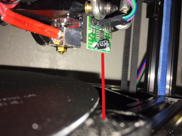
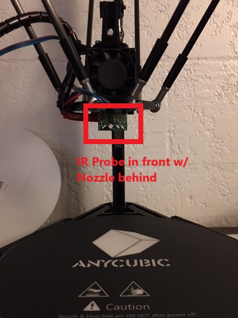
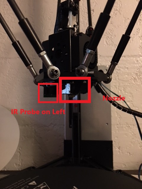
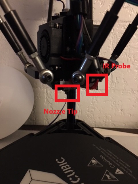
      • The auto probe calibration works with the Z probe except for the far XY edge where it drags along the bed (the IR sensor is positioned off the side of the bed - it sees nothing so the nozzle eats the bed). This is amazing progress, though. Because reterminating the IR Z probe connectors got it to work (in theory).

      • However, it looks like the printer still thinks that Z=5.3 is the same thing as Z=0. When I try to print something like the XYZ calibration cube, the nozzle drops down to Z5.30 (5.3mm above the bed) and spews filament onto the bed. Recalibrating (and entering M500 to save settings) doesn't resolve the issue. What might be causing this stubborn behavior in the printer?

      Here are my config files:

      config.g:

      ; Configuration file for Duet WiFi (firmware version 1.20 or newer)
      ; executed by the firmware on start-up
      ;
      ; generated by RepRapFirmware Configuration Tool on Sun May 13 2018 19:16:40
      
      ; General preferences
      G90					; Send absolute coordinates...
      M83					; ...but relative extruder moves
      M555 P1					; Set firmware compatibility to look like RepRapFirmare
      
      ;*** The homed height is deliberately set too high in the following - you will adjust it during calibration.
      M665 R134 L270 B85 H285		; Set delta radius, diagonal rod length, printable radius and homed height
      M666 X0 Y0 Z0			; Put your endstop adjustments here, or let auto calibration find them
      
      ; Network
      M550 Pduettest
      M552 S1					; Enable network
      M586 P0 S1				; Enable HTTP
      M586 P1 S0				; Disable FTP
      M586 P2 S0				; Disable Telnet
      
      ; Z-Probe
      M558 P1 X0 Y0 Z0 H30 F1000 T5000 ;I1 		; Set Z probe type to DC42 and the dive height + speeds
      G31 X0 Y0 Z2.02 P500				; Set Z probe trigger value, offset and trigger height
      M557 R130 S20					; Define mesh grid
      
      ; Drives 
      M569 P0 S1					; Drive 0 goes forwards
      M569 P1 S1					; Drive 1 goes forwards
      M569 P2 S1					; Drive 2 goes forwards
      M569 P3 S1					; Drive 3 goes forwards
      M350 X16 Y16 Z16 E16 I1				; Configure microstepping with interpolation
      M92 X80 Y80 Z80 E96				; Set steps per mm
      M566 X1200 Y1200 Z1200 E1200			; Set maximum instantaneous speed changes (mm/min)
      M203 X18000 Y18000 Z18000 E1200			; Set maximum speeds (mm/min)
      M201 X1000 Y1000 Z1000 E1000			; Set accelerations (mm/s^2)
      M906 X1000 Y1000 Z1000 E800 I30			; Set motor currents (mA) and motor idle factor in per cent
      M84 S30						; Set idle timeout
      
      ; Axis Limits
      M208 Z0 S1					; Set minimum Z
      
      ; Endstops
      M574 X2 Y2 Z2 S1				; Set active high endstops
      
      ; Heaters
      M305 P0 T100000 B4267 C0 R4700			; Set thermistor + ADC parameters for heater 0
      M143 H0 S120					; Set temperature limit for heater 0 to 120C
      M305 P1 T100000 B4267 C0 R4700			; Set thermistor + ADC parameters for heater 1
      M143 H1 S275					; Set temperature limit for heater 1 to 275C
      
      ; Fans
      M106 P0 S0.3 I0 F500 H-1 ; Set fan 0 value, PWM signal inversion and frequency. Thermostatic control is turned off
      M106 P1 S1 I0 F500 H1 T45 ; Set fan 1 value, PWM signal inversion and frequency. Thermostatic control is turned on
      M106 P2 S1 I0 F500 H1 T45 ; Set fan 2 value, PWM signal inversion and frequency. Thermostatic control is turned on
      
      ; Tools
      M563 P0 D0 H1					; Define tool 0
      G10 P0 X0 Y0 Z0					; Set tool 0 axis offsets
      G10 P0 R0 S0					; Set initial tool 0 active and standby temperatures to 0C
      
      ; Automatic saving after power loss is not enabled
      M501
      ; Custom settings are not configured
      

      config-override.g:

      ; This is a system-generated file - do not edit
      ; Delta parameters
      M665 L270.000 R134.000 H285.000 B85.0 X0.000 Y0.000 Z0.000
      M666 X0.000 Y0.000 Z0.000 A0.00 B0.00
      ; Heater model parameters
      M307 H0 A90.0 C700.0 D10.0 S1.00 V0.0 B1
      M307 H1 A340.0 C140.0 D5.5 S1.00 V0.0 B0
      M307 H2 A340.0 C140.0 D5.5 S1.00 V0.0 B0
      M307 H3 A340.0 C140.0 D5.5 S1.00 V0.0 B0
      M307 H4 A340.0 C140.0 D5.5 S1.00 V0.0 B0
      M307 H5 A340.0 C140.0 D5.5 S1.00 V0.0 B0
      M307 H6 A340.0 C140.0 D5.5 S1.00 V0.0 B0
      M307 H7 A340.0 C140.0 D5.5 S1.00 V0.0 B0
      

      bed.g:

      ; bed.g
      ; called to perform automatic delta calibration via G32
      ;
      ; generated by RepRapFirmware Configuration Tool on Sun May 13 2018 19:16:40
      M561 			; clear any bed transform
      G31 X0 Y0		; don't want any probe offset for this - ADDED 5/21/2018
      G28			; home the printer
      M401			; deploy the Z probe
      
      ; bed.g file for RepRapFirmware, generated by Escher3D calculator
      ; 10 points, 6 factors, probing radius: 105, probe offset (0, 0)
      ;M98 Pdeployprobe.g
      G30 P0 X0.00 Y105.00 Z-99999 H0
      G30 P1 X90.93 Y52.50 Z-99999 H0
      G30 P2 X90.93 Y-52.50 Z-99999 H0
      G30 P3 X0.00 Y-105.00 Z-99999 H0
      G30 P4 X-90.93 Y-52.50 Z-99999 H0
      G30 P5 X-90.93 Y52.50 Z-99999 H0
      G30 P6 X0.00 Y52.50 Z-99999 H0
      G30 P7 X45.47 Y-26.25 Z-99999 H0
      G30 P8 X-45.47 Y-26.25 Z-99999 H0
      G30 P9 X0 Y0 Z-99999 S6
      ;M98 Pretractprobe.g
      
      ; DEFAULT SETTINGS - Set by the RepRapFirmware Wizard
      ; Probe the bed at 3 peripheral and 0 halfway points, and perform 3-factor auto compensation
      ; Before running this, you should have set up your Z-probe trigger height to suit your build, in the G31 command in config.g.
      ;G30 P0 X0 Y84.9 H0 Z-99999
      ;G30 P1 X73.53 Y-42.45 H0 Z-99999
      ;G30 P2 X-73.53 Y-42.45 H0 Z-99999
      ;G30 P3 X0 Y0 Z-99999 S3 ;H0
      
      M402 ; retract the Z probe
      
      G1 X0 Y0 Z150 F15000 ; get the head out of the way of the bed
      

      homedelta.g

      ; homedelta.g
      ; called to home all towers on a delta printer
      ;
      ; generated by RepRapFirmware Configuration Tool on Sun May 13 2018 19:16:40
      G91                        ; relative positioning
      G1 S1 X400 Y400 Z400 F1800 ; move all towers to the high end stopping at the endstops (first pass)
      
      G1 X-5 Y-5 Z-5 F1800 S2    ; go down a few mm
      G1 S1 X10 Y10 Z10 F360     ; move all towers up once more (second pass)
      G1 Z-5 F6000               ; move down a few mm so that the nozzle can be centred
      G90                        ; absolute positioning
      ;G1 X0 Y0 F6000            ; move X+Y to the centre
      

      Any suggestions? Thanks!

      posted in Duet Hardware and wiring
      mindbender9undefined
      mindbender9
    • RE: Beginner Needs Help - Anycubic Kossel Plus + Duet WiFi -- HOW?

      @danal said in Beginner Needs Help - Anycubic Kossel Plus + Duet WiFi -- HOW?:

      homedelta.g should have much larger values in the first G1 command larger than the physical printer, so that the carriages go all the way to the switches, something like

      G1 S1 X400 Y400 Z400 F1800

      Thanks @Danal - I'll update homedelta.g when I get home.

      Is this related to why the "G30 S-1" command to bury the nozzle hard into the bed (when it shouldn't move the Z position)?

      posted in Duet Hardware and wiring
      mindbender9undefined
      mindbender9
    • RE: Beginner Needs Help - Anycubic Kossel Plus + Duet WiFi -- HOW?

      @dc42 said in Beginner Needs Help - Anycubic Kossel Plus + Duet WiFi -- HOW?:

      That suggests that either you have connected the OUT pin of the IR sensor to the wrong pin, or there is a bad connection in that wire. It should be connected to the pin labelled IN on the Probe connector. That's the pin on the opposite end of the connector to the 3.3V pin.

      Ah ok. Thanks @dc42 - I'll reterminate the wire when I get home.

      posted in Duet Hardware and wiring
      mindbender9undefined
      mindbender9
    • RE: Beginner Needs Help - Anycubic Kossel Plus + Duet WiFi -- HOW?

      So more weird results.

      I've attached the DC42 IR Sensor to the hot-end (effector?) and connected the sensor to the Duet following the instructions. I've changed my M558 P-value to P1 and followed the first half of the instructions on David's webpage for the IR sensor (Link).

      • If I put an object right near the bottom of the sensor, the LED lights up solid. I take my hand away, the LED turns off. Nice.

      • On the Duet device webpage, the Z-Probe value remains at a value of 280 no matter what the Z-height is. It fluctuates between 279-280, and that's it.

      • With 12V power applied, I enter M558 P1 then I enter G31 P500 Z1.0 on the G-Console. After setting the Z-height manually with 2 sheets of paper, I raise the nozzle 5mm up as instructed, then G92 Z0 to set Z=0.

      • Following the instructions, I enter G30 S-1 and the nozzle buries itself into the bed again HARD. Here's a screenshot of the Console:

      0_1528869066630_IR_Sensor_Trbl1.JPG

      • If I press "Home All" the assembly raises itself up to the top but doesn't click the end-stops. I then get an error:
      G28
      Error: G0/G1: insufficient axes homed
      Error: Homing failed
      

      Here's the config files:

      • config-override.g (I commented the weird values out again):
      ; This is a system-generated file - do not edit
      ; Delta parameters
      ;M665 L271.000 R152.869 H301.792 B85.0 X6.799 Y4.280 Z0.000
      ;M666 X2.286 Y-0.607 Z-1.679 A0.00 B0.00
      ; Heater model parameters
      M307 H0 A90.0 C700.0 D10.0 S1.00 V0.0 B1
      M307 H1 A340.0 C140.0 D5.5 S1.00 V0.0 B0
      M307 H2 A340.0 C140.0 D5.5 S1.00 V0.0 B0
      M307 H3 A340.0 C140.0 D5.5 S1.00 V0.0 B0
      M307 H4 A340.0 C140.0 D5.5 S1.00 V0.0 B0
      M307 H5 A340.0 C140.0 D5.5 S1.00 V0.0 B0
      M307 H6 A340.0 C140.0 D5.5 S1.00 V0.0 B0
      M307 H7 A340.0 C140.0 D5.5 S1.00 V0.0 B0
      
      • config.g:
      ; Configuration file for Duet WiFi (firmware version 1.20 or newer)
      ; executed by the firmware on start-up
      ;
      ; generated by RepRapFirmware Configuration Tool on Sun May 13 2018 19:16:40
      
      ; General preferences
      G90					; Send absolute coordinates...
      M83					; ...but relative extruder moves
      M555 P1					; Set firmware compatibility to look like RepRapFirmare
      
      ;*** The homed height is deliberately set too high in the following - you will adjust it during calibration.
      M665 R134 L270 B85 H285		; Set delta radius, diagonal rod length, printable radius and homed height
      M666 X0 Y0 Z0			; Put your endstop adjustments here, or let auto calibration find them
      
      ; Network
      M550 Pduettest
      M552 S1					; Enable network
      M586 P0 S1				; Enable HTTP
      M586 P1 S0				; Disable FTP
      M586 P2 S0				; Disable Telnet
      
      ; Z-Probe
      M558 P1 X0 Y0 Z0 H5 F1000 T5000 ;I1 		; Set Z probe type to DC42 and the dive height + speeds
      G31 X0 Y0 Z1.0 P500				; Set Z probe trigger value, offset and trigger height
      M557 R130 S20					; Define mesh grid
      
      ; Drives 
      M569 P0 S1					; Drive 0 goes forwards
      M569 P1 S1					; Drive 1 goes forwards
      M569 P2 S1					; Drive 2 goes forwards
      M569 P3 S1					; Drive 3 goes forwards
      M350 X16 Y16 Z16 E16 I1				; Configure microstepping with interpolation
      M92 X80 Y80 Z80 E96				; Set steps per mm
      M566 X1200 Y1200 Z1200 E1200			; Set maximum instantaneous speed changes (mm/min)
      M203 X18000 Y18000 Z18000 E1200			; Set maximum speeds (mm/min)
      M201 X1000 Y1000 Z1000 E1000			; Set accelerations (mm/s^2)
      M906 X1000 Y1000 Z1000 E800 I30			; Set motor currents (mA) and motor idle factor in per cent
      M84 S30						; Set idle timeout
      
      ; Axis Limits
      M208 Z0 S1					; Set minimum Z
      
      ; Endstops
      M574 X2 Y2 Z2 S1				; Set active high endstops
      
      ; Heaters
      M305 P0 T100000 B4267 C0 R4700			; Set thermistor + ADC parameters for heater 0
      M143 H0 S120					; Set temperature limit for heater 0 to 120C
      M305 P1 T100000 B4267 C0 R4700			; Set thermistor + ADC parameters for heater 1
      M143 H1 S275					; Set temperature limit for heater 1 to 275C
      
      ; Fans
      M106 P0 S0.3 I0 F500 H-1 ; Set fan 0 value, PWM signal inversion and frequency. Thermostatic control is turned off
      M106 P1 S1 I0 F500 H1 T45 ; Set fan 1 value, PWM signal inversion and frequency. Thermostatic control is turned on
      M106 P2 S1 I0 F500 H1 T45 ; Set fan 2 value, PWM signal inversion and frequency. Thermostatic control is turned on
      
      ; Tools
      M563 P0 D0 H1					; Define tool 0
      G10 P0 X0 Y0 Z0					; Set tool 0 axis offsets
      G10 P0 R0 S0					; Set initial tool 0 active and standby temperatures to 0C
      
      ; Automatic saving after power loss is not enabled
      M501
      ; Custom settings are not configured
      

      homedelta.g:

      ; homedelta.g
      ; called to home all towers on a delta printer
      ;
      ; generated by RepRapFirmware Configuration Tool on Sun May 13 2018 19:16:40
      
      G91                        ; relative positioning
      G1 S1 X290 Y290 Z290 F1800 ; move all towers to the high end stopping at the endstops (first pass)
      
      G1 X-5 Y-5 Z-5 F1800 S2    ; go down a few mm
      G1 S1 X10 Y10 Z10 F360     ; move all towers up once more (second pass)
      G1 Z-5 F6000               ; move down a few mm so that the nozzle can be centred
      G90                        ; absolute positioning
      ;G1 X0 Y0 F6000            ; move X+Y to the centre
      

      Entering the command "G30 S-1" is hanging me up. I've tried to do an auto-calibration and the nozzle took a number of measurements in the air above the bed ranging from 3mm - 130mm.

      Can anyone make sense of this? I have not resolved the bed angle issue yet, but this is something else entirely. Please help! Thanks!

      posted in Duet Hardware and wiring
      mindbender9undefined
      mindbender9
    • RE: Beginner Needs Help - Anycubic Kossel Plus + Duet WiFi -- HOW?

      @danal said in Beginner Needs Help - Anycubic Kossel Plus + Duet WiFi -- HOW?:

      Having said that, I would NOT take your machine apart again.

      LOL - No argument here.

      And, just checking basic assumptions: You have M665 L271, correct?

      Yes, config.g still has M665 L271 set. I'm working on the bed issues and will remove the stock bed mounts and pursue the direct attached method.

      Thanks for the help! I'll start up a test print when I get home from work.

      posted in Duet Hardware and wiring
      mindbender9undefined
      mindbender9
    • RE: Beginner Needs Help - Anycubic Kossel Plus + Duet WiFi -- HOW?

      @juice - How long has it been since you've purchased the AC Kossel? If it's still under warranty, you could pursue getting a replacement part for that single arm.

      On second thought, trying to get tech support from Anycubic3D wasn't easy. You might have better luck going through the seller for a replacement part under warranty.

      Otherwise, several people have recommended carbon fiber aftermarket arms/ball ends as being one of the best upgrades for a delta printer. When I get my printer to work, I might look at replacement arms as a future purchase.

      posted in Duet Hardware and wiring
      mindbender9undefined
      mindbender9
    • RE: Beginner Needs Help - Anycubic Kossel Plus + Duet WiFi -- HOW?

      Hi @Juice

      If you mean the arms, I disassembled them from the Nozzle/Hot-End and the slider assemblies. Then I measured each using a ruler, and they were all uniform in length.

      But I more or less used your diagram (thank you for that) and eyeballed to center position in each eye.

      Getting the arms reattached took a little work.

      posted in Duet Hardware and wiring
      mindbender9undefined
      mindbender9
    • RE: Beginner Needs Help - Anycubic Kossel Plus + Duet WiFi -- HOW?

      Measuring Eyehole to Eyehole, the arms are 270-271mm in length.

      @3mm - You were right on the money regarding the floating nuts. I was able to reattach all of the arms after removing the sliders like you mentioned. Thanks again.

      @Danal - I set all three sliders and endstops to the same position equally. One slider arm was slightly off by 1mm compared to the other two, but now they're all evenly set.

      I want to recheck the three main pillars again before performing a test calibration. Just to be safe.

      Thanks guys for all of the help. Believe me, I am very grateful for all of the tips and direction you're sending my way. I would be (more) lost if you guys weren't jumping in to help.

      Much appreciated as always!

      posted in Duet Hardware and wiring
      mindbender9undefined
      mindbender9