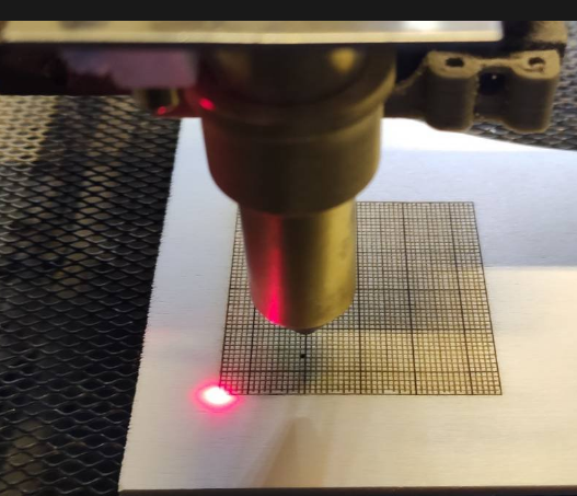
To align the worksheet exactly I installed and red laser diode parallel to the laser beam after the last mirror.
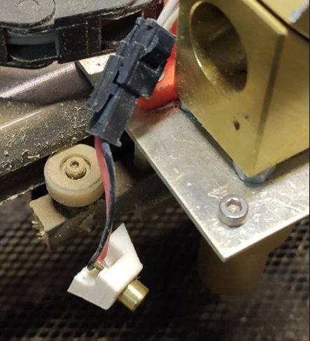
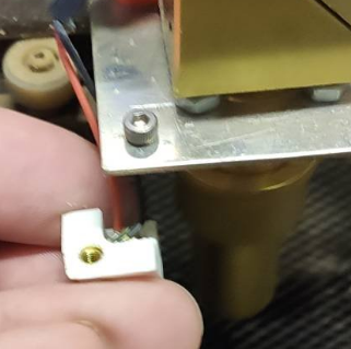
The wiring was easy, I just use an available fan2 connector and the 5V my BTT SKR 2 board offers and connect this directly to the laser diode.
To activate the pin I add in config.g
; Tools --> red dot Laser
M950 F2 C"fan2" Q100                             ; create red dot laser as 2 on pin fan2
M106 P2 S0 C"RED Laser" H-1                 ; set red dot laser to off on startup --> controlled by macros
To use it I create two macros, first LASER ON with the following content:
G10 L2 X0 Y0                        ; Reset workplace coordinates to zero

; Move laser head by red laser offset
G1 F5000 X{move.axes[0].machinePosition + 14.5} Y{move.axes[1].machinePosition + 8.5}

M106 P2 S0.7                        ; switch on red laser diode to 70% brightness
and the LASER OFF which contains:
; move main laser headto current red laser position
G1 F5000 X{move.axes[0].machinePosition - 14.5} Y{move.axes[1].machinePosition - 8.5}

; set the current position as X and Y zero position
G10 L20 P1 X0 Y0

M118 P3 S"Workplace zero set"

; switch of red laser
M106 P2 S0
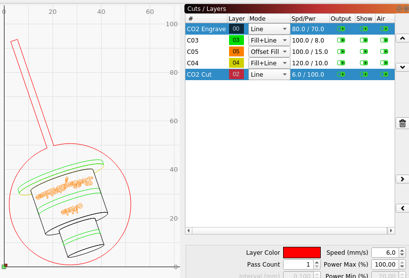
To find the right values for your offset here is an SVG which you can use to engrave a 50x50mm raster:

To get your values just engrave the raster and then run LASER ON macro, place the red dot in direction where your ZERO is configured (mine is front left) and then fire your laser, then read the offset and change the values in LASER ON and LASER OFF macro.
Hopefully someone else find this feature useful too