@dc42
hi,
Got it to work. There was issue with bent contacts in one of those sockets.
Thank you for the advice.
Best posts made by Sophiechka
-
RE: Help in errors between Duet 3 6hc & 1XDposted in General Discussion
Latest posts made by Sophiechka
-
extruder motor not workingposted in General Discussion
Hello
I am having problem with my extruder motor, could you advice me on how to solve this issue please.
I have built Hangprinter with Duet 3 6HC and five stepper motor. Four Nema 23 for A, B, C, D motors and a Nema 34 for the extruder. All the motors work when i send g.code command except for the extruder motor. It seems Web controller doesn't recognise the extruder driver as the extruder controller on the Web Control is grey. I have check the connection and the motor itself and they are working.
Below is my config.g and the set up of the wire connection I have at the moment.Thank you
SophiaConfig.g file :
; Enable network
; M552 S1
M552 S1 P192.168.50.101
M550 P"hangprinter" ; change the name from the IP address of 192.168.50.101;General Machine Settings/Conventions
G21 ;work in mm
G90 ;absolute coordinates
M83 ;relative extruder moves
;G4 S2 ; wait for expansion boards to start;Heaters and Temp Sensor
;bandheater
;M140 H-1 ; disable heated bed (overrides default heater mapping)
;M308 S1 P"temp0" Y"pt1000" A"Extruder Sensor"; configure sensor 1 as PT1000 on pin temp1
;M950 H1 C"out1" Q10 T1 ; create nozzle heater output on out1 and map it to sensor 1, limit pwm frequency to 10Hz
;M307 H1 B0 R0.050 C1800 D36.57 S1.00 V12.1 ; FAILED AUTOTUNE RESULTS ; disable bang-bang mode for heater and set PWM limit
;M307 H1 B0 R0.319 C1028.9 D36.57 S1.00 V12.1 ; AUTOTUNE RESULTS FROM 2022-03-26
;M143 H1 S300 ; set temperature limit for heater 0 to 240C;second temp sensor
;M308 S2 P"temp0" Y"pt1000" A"Barrel Sensor"; configure sensor 2 as PT1000 on pin temp2;Fans
;Heatsink Fans 1 and 2
;M950 F1 C"!out4+out4.tach" Q25000 ; Fan 1 uses out4, but we are using a PWM fan so the output needs to be inverted, and using out4.tach as a tacho input
;M106 P1 H-1
;M950 F2 C"!out5+out5.tach" Q25000 ; Fan 2 uses out5, but we are using a PWM fan so the output needs to be inverted, and using out5.tach as a tacho input
;M106 P2 H-1;Kinematics and Drives
;Drives: x4 NEMA23's for Hangprinter Axis and x1 NEMA34 for extruderM18 ;disable default driver assignments;
M569 P0 S0 ; drive 0 for extruder axis
M569 P1 S1 ; drive 1 (X motor output aka A) goes forwards
M569 P2 S1 ; drive 2 (Y motor output aka B) goes forwards
M569 P3 S1 ; drive 3 (Z motor output aka C) goes forwards
M569 P4 S0 ; drive 4 for D axis, goes forwards; need to create another "U" axis for D motor
;M569 P5 S0 ; drive 5 (feeder motor) goes backwards (CW looking from behind motor )M584 X1 Y2 Z3 E0 U4 ;assign drives to axes and create U axis for D motor. Feeder motor is assigned as a second extruder hence E0:5 where 5 is stepper drive 5 which feed motor is connected
;Step settings
M350 X16 Y16 Z16 U16 E16 I1 ; configure microstepping with interpolation
;M92 X192 Y192 Z192 U192 ; set steps/mm for each spool. DO NOT CHANGE THIS PARAMETER
M92 E1000 ; set steps/mm for extruder and feed motor;Speed and Accelerations
M566 X250.00 Y250.00 Z250.00 U250.0 E200.00 ; set maximum instantaneous speed changes (mm/min)
M203 X6000.00 Y6000.00 Z6000.00 U6000.00 E9000.00 ; set maximum speeds (mm/min)
M201 X500.00 Y500.00 Z500.00 U250.00 E200.00 ; set accelerations (mm/s^2);Set Currents
M906 X2500 Y2500 Z2500 E3000 U2500 I30 ; set motor currents (mA) and motor idle factor in per cent
M84 S30 ; Set idle timeout;Kinematics
M669 K6 ; Configures the Duet 3 to identify as Hangprinter Kinematics;set anchor distances
M669 K6 A0.0:-1596.0:-68.0 B1388.0:802.0:-68.0 C-1382.0:797.0:-68.0 D0.0:0.0:2660.0 ; set Hangprinter kinematics parameters
M669 P1000.0 ; Hangprinter printable radius (unused for now)
M669 S100 T0.5 ; Segments per second and min segment lengthM666 Q0.0033333 ; buildup compensation factor for ABCD
M666 R75.0:75.0:75.0:75.0 ; ABCD radii
M666 U2:2:2:4 ; Mechanical advantages on ABCD spools - 2 stands for doubled lines
M666 O1:1:1:1 ; Number of lines per spool or "coil mode" (each line has it's own coil). 1 = coil style
M666 L20:20:20:20 ; Motor gear teeth of ABCD axes
M666 H254:254:254:254 ; Spool gear teeth of ABCD axes...CAN TUNE THIS AS NEEDED TO GET RIGHT MOVEMENT
M666 J200:200:200:200 ; Full steps per ABCD motor revolution ...CAN TUNE THIS AS NEEDED TO GET RIGHT MOVEMENTM208 S0 Z1540 ; maximum height 1750mm or some distance below D anchor. CHANGE THIS ACCORDING TO YOUR SETUP
M208 S1 Z-2 ; minimum height -5mm; Uncomment M564 S0 if you don't want G0/G1 moves to be limited to a software defined volume
; M564 S0; Tool Definitions
M563 P0 D0 ;assign extruder drive(D0), if you have Heater or Fan assign as Heater (h1) and Fan(F1) to tool0(P0),
G10 P0 R0 S0 ;set initial tool0 active and standby temperatures to 0C
;M568 P0 S1 ;enable mixing for tool 0
;M567 P0 E1:0.05 ;set mixing ratios for tool 0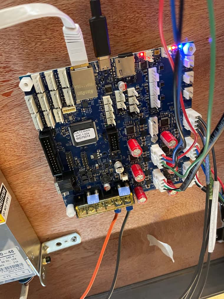
-
RE: Duet3 6HC v1.02 and laterposted in Duet Hardware and wiring
@dc42 hello
thank you for the info. I will use V48. would V48 goes in the range of the power voltage well below the stepper driver rating of 60V?If I use one NEMA 34 and four NEMA 23 together with the Duet3 6HC v1.02, would the correct/sufficient voltage will be distributed to the stepper motors by the driver? e.g V48 for NEMA 34 and V36 for NEMA 23
-
RE: Duet3 6HC v1.02 and laterposted in Duet Hardware and wiring
Thank you. Since the input voltage is the output voltage, I just need to make sure to buy the Duet 3 Mainboard 6HC with version 1.02 or later.
Is it possible to have an external power supply or a higher voltage than 48V for the stepper driver? As the maximum voltage the stepper driver can handle is 60V?
-
Duet3 6HC v1.02 and laterposted in Duet Hardware and wiring
Hi, In the Duet3 documentation (https://docs.duet3d.com/Duet3D_hardware/Duet_3_family/Duet_3_Mainboard_6XD_Hardware_Overview) have read that the maximum voltage intput for Duet 3 Mainboard 6HC v1.02 and later is V48. Not 32V. Is the version written on the board? How do I know which version I would be buying?
I am hoping to use a stepper motor, either NEMA 34 or stronger, with the Duet 3 Mainboard 6HC. Does the board have the same output voltage as the input?
If not, can I add an external power supply to the stepper motor?
-
RE: command/G-code for the extrusion controllerposted in General Discussion
hi,
Sorry about the late reply. Thank you for the advice. i've sent M302 P1 and then G1 E2000 F1000 it worked.
It's a bit of a different question is it possible to bypass the homeing function? I am printing a shape on top of the printed shape. And when I tried to print the second shape on top of the first shape after the first shape was finished, I got an error saying, "Error: G0/G1: insufficient axes homed". I could send G92 X0 Y0 Z0, but wouldn't this command make the printer think its position is the home position in the config.g? making it poor calibration?
-
RE: command/G-code for the extrusion controllerposted in General Discussion
Here is my config.g file. I have commented out the heater, fan and thermistors as I don't have any of them. With M302 P1 command, if it works with my config.g sending e.g M302 P1 G1 E500 F1000 will retract the extruder?
; Communication and general
G21 ; Work in millimetres
G90 ; Send absolute coordinates...
M83 ; ...but relative extruder moves; Kinematics
G4 S1 ; Wait 1 second because expansion boards might not be ready to receive CAN signal yet.
M584 X40.0 Y41.0 Z42.0 U43.0 P4 ; map ABCD-axes to CAN addresses, and set four visible axes. Please excuse that ABCD motors are called XYZU here.
M584 E0:1:2:3:4:5 ; Regard all built in stepper drivers as extruder drives
M669 K6 ; "This is a Hangprinter"
M669 P2000.0 ; Printable radius (unused by Hangprinters for now)
M669 S430 T0.1 ; Segments per second and min segment length; Output of auto calibration script for Hangprinter
M669 A0.0:-1610.98:-131.53 B1314.22:1268.14:-121.28 C-1415.73:707.61:-121.82 D-0.00:0.01:2299.83
M666 Q0.128181 R75.546:75.659:76.128:75.192
; Explanation:
; ; M669 defines the positions of the anchors, expressed as X:Y:Z distances between a line's pivot points, when the machine is homed.
; ; M666 sets Q=spool buildup, R=spool radii (incl buildup, when homed)M208 Z2000.00 ; set maximum Z somewhere below D anchor. See M669 ... D<number>
M208 S1 Z-10.0 ; set minimum Z; The following values must also be in the auto calibration script for Hangprinter (if you plan to use it)
M666 U2:2:2:4 ; Mechanical advantages on ABCD
M666 O1:1:1:1 ; Number of lines per spool
M666 L20:20:20:20 ; Motor gear teeth of ABCD axes
M666 H255:255:255:255 ; Spool gear teeth of ABCD axes; Flex compensation
M666 W1.0 ; Mover weighs 1 kg. Set to 0 to disable flex compensation.
M666 S20000.0 ; Spring constant (rough approximation) for Garda 1.1 mm line (unit N/m).
; The real value is somewhere between 20k and 100k.
; Lower value gives more flex compensation.
M666 I0.0:0.0:0.0:0.0 ; Min planned force in four directions (unit N).
; This is a safety limit. Should affect only exceptional/wrong moves,
; for example moves outside of the reachable volume.
M666 X70.0:70.0:70.0:70.0 ; Max planned force in four directions (unit N)
; This is a safety limit. Will affect moves close to
; the limits of the reachable volume.
M666 T10.0 ; Desired target force (unit N).
; The flex compensation algorithm aims for at least
; this amount of fource in the ABC line directions at all times.
; It can be thought of as a minimum pre-tension value.
; It's recommended to set it around 10 times higher
; than your W (mover weight in kg) value.; Guy wire lengths. Needed for flex compenation.
; Guy wires go between spool and final line roller.
; If your spools are all mounted on the D-anchor, on the ceiling plate, then you're all good,
; and you don't need to configure M666 Y values explicitly.
; If your spools are not all on the D-anchor then you must measure guy wire
; lengths and set them here.
; If your spools are all mounted on their respective anchors, so that you have no guy wires,
; then you should configure zeroed guy wire lengths M666 Y0.0:0.0:0.0:0.0.
;M666 Y-1.0:-1.0:-1.0:-1.0; Torque constants. These are required for reading motor forces from ODrives
; They are the same values as is configured in the ODrives themselves (8.27/330 for motors in the standard HP4 BOM)
;M666 C0.025061:0.025061:0.025061:0.025061; Uncomment M564 S0 if you don't want G0/G1 moves to be be limited to a software defined volume
; M564 S0; Drives
M666 J25:25:25:25 ; Full steps per ABCD motor revolution (match with ODrives...)M569 P0 S1 ; Drive 0 goes forwards
M569 P1 S1 ; Drive 1 goes forwards
M569 P2 S1 ; Drive 2 goes forwards
M569 P3 S1 ; Drive 3 goes forwards
M569 P4 S1 ; Drive 4 goes forwards
M569 P5 S1 ; Drive 5 goes forwards;; Warning: On a Hangprinter, ABCD motor directions shouldn't be changed, at least not
;; via this config.g file.
;; They are duplicated and hard coded into the firmware
;; to make ODrive's torque mode go the right way.
;; Please connect BLDC wires, from left to right, looking at the board
;; from the front, so that ODrive silk screen is readable from left to right:
;; |---------------------------------------------------------------|
;; |DC |
;; |- ODrive |
;; |+ |
;; | AUX |
;; |--||---||---||------------------------------------||---||---||-|
;; || || || || || ||
;; ALT 1: Black, Red, Blue Black, Red, Blue
;; ALT 2: Yellow, Black, Red Yellow, Black, RedM569 P40.0 S1 ; Drive 40.0 (A) goes forwards
M569 P41.0 S1 ; Drive 41.0 (B) goes forwards
M569 P42.0 S0 ; Drive 42.0 (C) goes backwards
M569 P43.0 S0 ; Drive 43.0 (D) goes backwards; Speeds and accelerations
M201 X10000 Y10000 Z10000 U10000 E1000 ; Max accelerations (mm/s^2)
M203 X36000 Y36000 Z36000 E3600 ; Max speeds (mm/min)
M204 P2000 T4000 ; Accelerations while printing and for travel moves
M566 X240 Y240 Z1200 E1200 ; Maximum instant speed changes mm/minute; Currents
M906 E1400 I60 ; Set motor currents (mA) and increase idle current to 60%; Endstops
M574 X0 Y0 Z0 ; set endstop configuration (no endstops); Thermistors and heaters
;M308 S1 P"temp0" Y"thermistor" T100000 B3950 ; Configure sensor 1 as thermistor on temp1
;M950 H1 C"out1" T1 ; create nozzle heater output on out1 and map it to sensor 1
;M307 H1 B0 S1.00 ; disable bang-bang mode for nozzle heater and set PWM limit
;M307 H1 A1271.9 C432.5 D8.2 V24 ; Set heater parameters (for Super Volcano 80W. You probably want to tune this yourself with M303.)
;M143 H1 S280 ; set temp limit for nozzle heater to 280C
;M570 S180 ; Hot end may be a little slow to heat up so allow it 180 seconds; Fans
;M950 F1 C"out7"
;M106 P1 X255 T45 H1 ; Enable Fan 1 thermostatic mode for sensor or heater 1 at 45 degrees
;M950 F0 C"out8" ; Defines a part cooling fan; Find "temp0" and "out7" pins in the wiring diagram:
; https://duet3d.dozuki.com/Wiki/Duet_3_Mainboard_6HC_Wiring_Diagram; Bltouch
; If you have a bltouch, see
; https://duet3d.dozuki.com/Wiki/Connecting_a_Z_probe#Section_BLTouch
; for how to install it
; Some of the commands below here might be different for you
; (eg if you don't have a Duet3 board, don't use the io7 headers, or have your bltouch mounted differently than me)
;M950 S0 C"io7.out"
;M558 P9 C"io7.in" H5 F120 T6000
;G31 X15 Y27 Z8 P25 ; Measure these values in your own setup.; These affect how you create and your mesh/grid bed compensation heightmap.csv values
; M557 X-200.001:200 Y-277.001:277 S80 ; Define a A2 sized grid with 1 cm margin...
; M376 H20 ; Taper the mesh bed compensation over 20 mm of z-height
; G29 S1 ; Load the default heightmap.csv and enable grid compensation; Tool definitions
M563 P0 D0 H1 ; Tool number 0, with extruder drive 0 uses heater 1 and no fan
G10 P0 S0 R0 ; Set initial tool 0 active at standby temperature 0; Miscellaneous
M92 E415 ; Set extruder steps per mm
M911 S10 R11 P"M913 X0 Y0 Z0 G91 M83 G1 Z3 E-5 F1000" ; set voltage thresholds and actions to run on power loss
T0 ; Select tool 0 -
command/G-code for the extrusion controllerposted in General Discussion
Hello
Recently i have been testing the clay extruder connected to the Driver0 on Duet 3 Mainboard 6HC. I have been clicking the 'retract' and 'extrude' button multiple times to push the plunger down to the correct position and to retract the plunger from the bottom of the cylinder after the print. Is there a command/G-code I can send instead? I've tried G1 E500 F1000, but nothing happened.
Here is my set up.
Best
Sophia -
RE: Help in errors between Duet 3 6hc & 1XDposted in General Discussion
@dc42
hi,
Got it to work. There was issue with bent contacts in one of those sockets.
Thank you for the advice. -
RE: Help in errors between Duet 3 6hc & 1XDposted in General Discussion
Hi, Thank you for the advice.
I have managed to changed all the address of the 1XD and they all work when then are individually connected to the main board. But when i connect then all four of them together, first two works (first image), LED from them sync with the main board and i can find them through DWC. But the other two 1XD board doesn't work. LED from these boards flash rapidly and continuously. I believe the wiring is correct. could there be another reason?

-
How to fix LED behaviour, data not going through CANposted in General Discussion
Hi,
I have Duet 3 Expansion 1XD connected to Duet 3 Mainboard 6HC.DWC wasn't recognising the 1XD, I thought i has something to do with can address, so I have tried to reset the 1XD to factory setting with jumper. But i don't think it got reset as during the process, I got LED behaviour and error codes - 4 times flesh.
The power of the main board is fine, and the status LED on the main board works, flashing per second. I think the CAN connection between the main board and the expansion board is ok as well. This is RJ11 I am using. it is not the High-Speed ADSL cables but i read this is not a problem. When I tested it with a cable test, it worked.
when I restarted the board without the jumper , status LED on the 1XD was flashing continuously and rapidly. DWC doesn't recognised 1XD.
What can i do to fix this?
