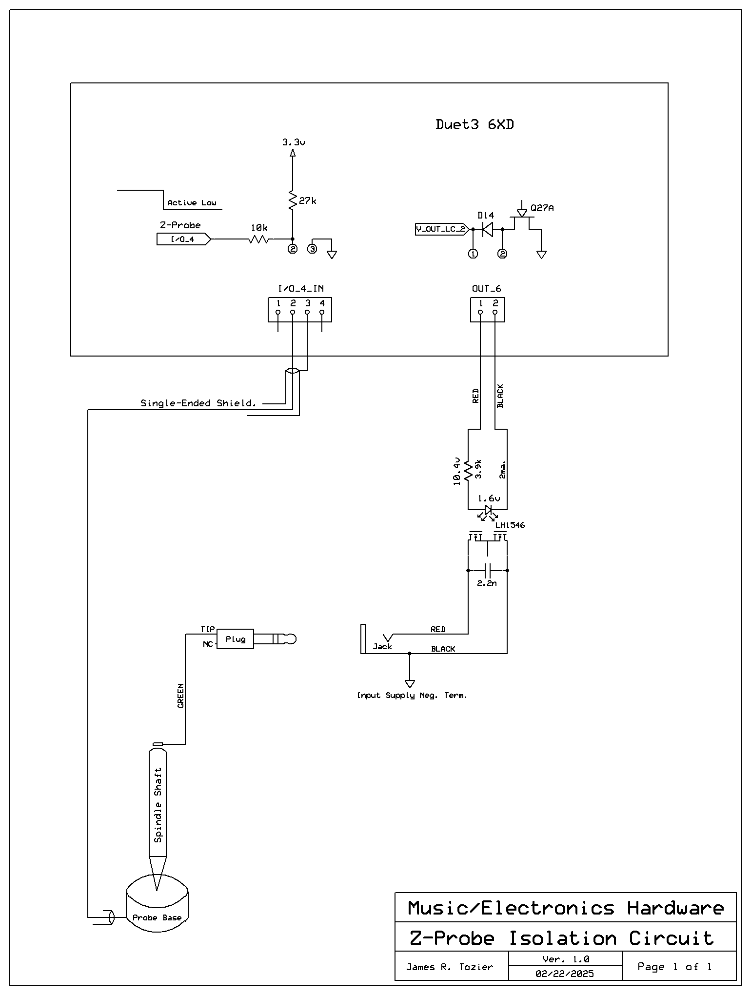
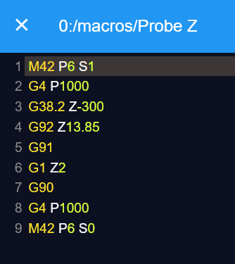
The simplest solution to my want of incorporating photo-optic end-stops, was to add a separate 24v supply for the 'PM-K45-P-C3' PNP sensor. Then simply connect its collector-output to one of the opto-isolated channels 5 thru 8. Testing of the X-axis was flawless and most accurate. No more mechanical switches. Now I just need to fabricate the mounting for all axes.
Best posts made by Valveman
-
RE: PNP Photo Sensors
Latest posts made by Valveman
-
RE: 6XD USB-C port gender
All fixed!
I cannot explain when or how, but config.g was gone. It took my [digital] son all of five minutes to find [that] to be the whole problem. Backups took care of it.
I just wish I had video of exactly how I caused it.
I must slow down and be much more careful. Now I can continue with my spindle. -
RE: 6XD USB-C port gender
Wow, what a quick and concise response to my situation. Many thanks for the guidance. But before I go any further, I want to do a re-work to the spindle motor power supply.
Simply put, it's nothing more than a 120vac rectified DC voltage regulator, using a single FET transistor that regulates the voltage from 0-100v. And while it works perfect for this light-duty cnc-router, it does not offer any electrical isolation from its input to output. The PWM to DC converter board that was chosen to couple the 6XD to that supply, offers no galvanic isolation either. In as much as things have been working fine for a very long time, I can't help but be concerned about the possibility of ground current being looped through the 6XD, via its 15vdc [isolated] supply, and that hot-line-side spindle supply. With the common wires disconnected, I measure some 27v between them. While all it takes is two fingers touching them to cancel out the meter reading, it's about the only issue I find, that might have caused the problem in the first place.
Replacing the PWM-DC unit with an opto-isolated version, the ground loop circuit will be broken. Then I will proceed with the business of trying to salvage my precious 6XD. Thanks for listening. -
RE: 6XD USB-C port gender
Members,
Slowly catching up. Lol. With YAT installed, and simply sending M552, I receive the following:
Ethernet is disabled, configured IP address: 0.0.0.0, actual IP address: 0.0.0.0<LF>ok<LF>
Again, a week ago the IP 192.168.5.227 eero was using, suddenly lost connection. CNC was powered on, but not moving. -
RE: 6XD USB-C port gender
@dc42
I'm not sure how to do that. Type M552 at the Command Prompt? That attempt results in just a non-recognized command. I have the cable plugged into the USBC port with no external power applied. The board has three led's lit; 5v, 3.3v, USB. And the normal blinking red status led. Please advise. -
RE: 6XD USB-C port gender
Update: I have my EERO working, as the left port works when connected to my PC. But there's no longer a connection being established when patched to the 6XD Ethernet port. Reiterating, the system was powered on and just idling, when the connection suddenly failed. I do not know how to troubleshoot the Duet, regarding IP addressing, or prove the Duet needing to be totally replaced. additionally, I was able to ping the EERO and get a good response. But pinging my Duet IP 192.168.5.227 returns nothing.
-
RE: 6XD USB-C port gender
@Valveman
Solved! My wife's phone cord fits it! So can I assume the cord is male and the pcb port is female? -
6XD USB-C port gender
Suddenly lost WiFi communication yesterday while resting idle. It was suggested that I connect via the USB-C port directly to my laptop, and try to prove the correct IP address. But I can't find a cable to do the job. Is that port male or female? What kind of a cable do I need to acquire?
-
RE: Z-Axis issues
Thanks for your insightful help. I'm a novice at programming this "new toy" of mine. I didn't realize that I should begin looking at homez.g, as I can readily see it's quite different from both the X and Y instructions. My son is the one doing all the code writing for me. I will have him look at it today, and then provide an update asap. Many thanks to you, for pointing me in the right direction.
-
Z-Axis issues
While all my new optical sensors work on my DIY cnc router, I still have a problem to solve with Z limit/home. May I start by needing to clearly understand the physical setup.
-X is to the left, and that's where we have the limit/end-stop sensor/switch positioned.
-Y is to the near/front, and that too, is where the limit/end-stop sensor/switch is positioned.
-Z is down [ toward the table], and we have its limit/end-stop up at the top, in the +Z direction.
When I home X, it travels to the far left, stops on the limit, moves a bit to the right, then stops a second time at the limit. Perfect. When I home Y, all the same movements take place, then stops perfectly.
But Z is all together different. When I home Z, it's required to move positive, to reach its limit position and then stop. And it never does like X-Y, back away then stop on the limit a second time. And that's not even the real big problem I have. While I can re-home X or Y by simply clicking on home, and watch each one move away and then right back to the perfect spot, Z does not.
Click Z home a second time, and it just plows upwards in the positive direction and jams the axis.
Shouldn't I be able to home Z like the others?
The only way I can operate, is to home Z, then move it away from its limit position, before attempting to home X-Y. That allows the Z the room/space to home a second time without crashing.
Is it because Z home is in the + direction?
I'm assuming some kind of code changes are required.
James