@dc42 That has indeed fixed the simulation errors for the LC filter. However the voltage across the resistor (fan) is still less than about 1V, no matter the PWM ratio.
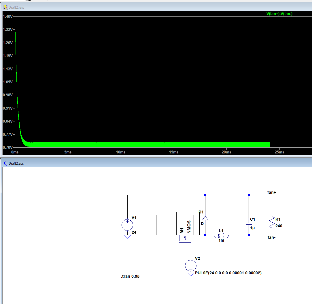
@dc42 That has indeed fixed the simulation errors for the LC filter. However the voltage across the resistor (fan) is still less than about 1V, no matter the PWM ratio.

@dc42 !
Okay so I tried recreating the LC circuit again on a fresh install of LT spice on a different PC. It did allow me to start simulation without the 100M resistor. Here is the new diagram:
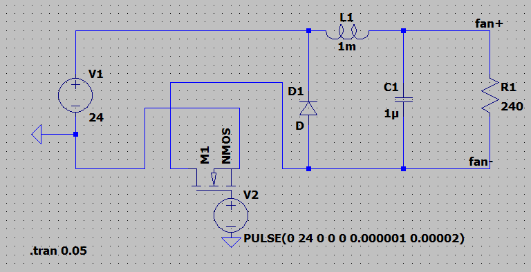
However when trying to simulate it, it freezes after less than 10 microseconds 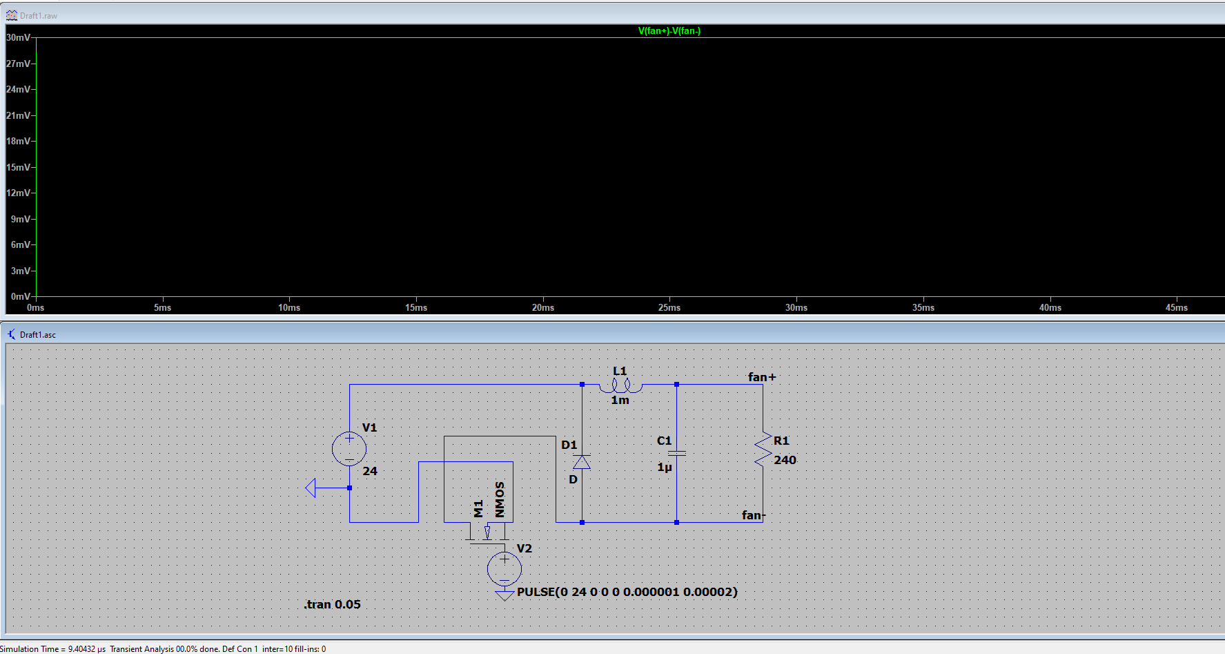
I tried removing the capacitor, giving this result: 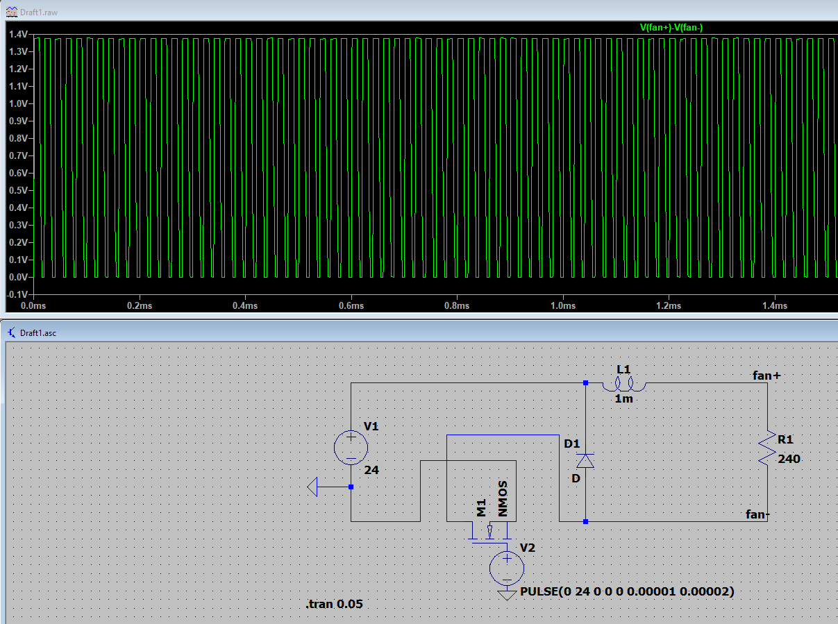
Turns out the waveform I measured the 26V spikes on was from the fan positive to actual ground, not the negative fan terminal, so you were right. My original statement saying that it is dangerous is wrong. However, the circuit is not working as expected (at least without the capacitor, no idea why it does not run with it), as if I change the PWM ratio, the average voltage stays the same. 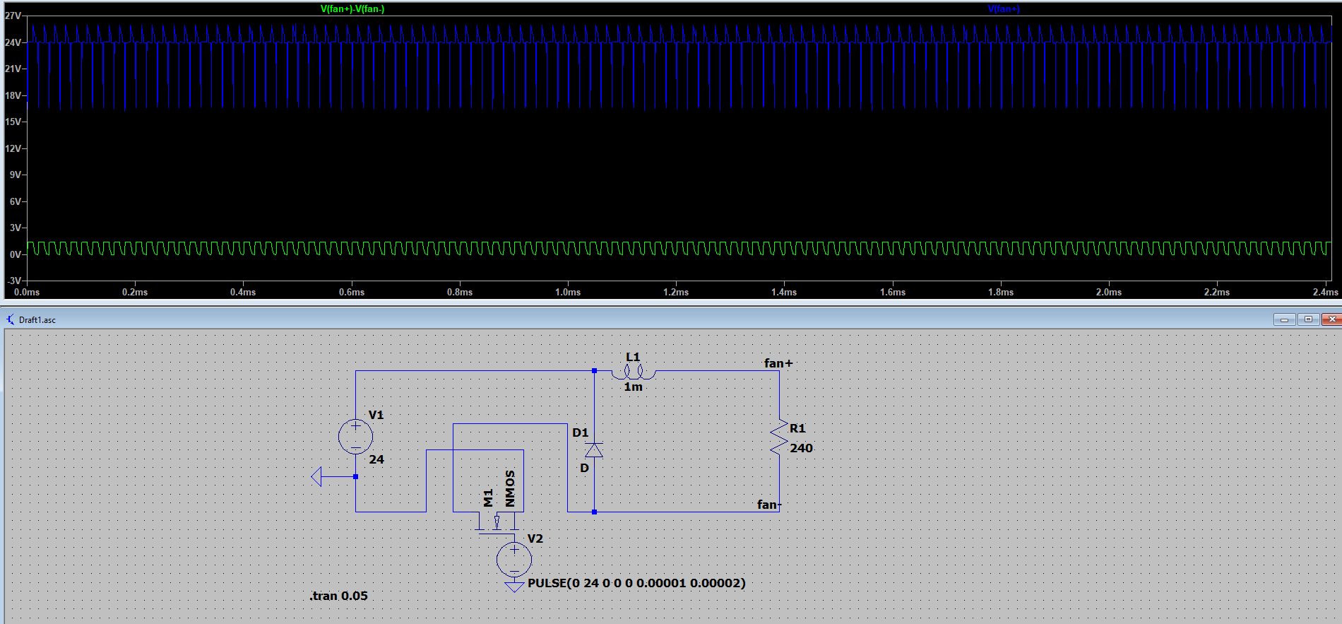
Edit: Managed to get it running with the capacitor. The extra 1GOhm does not affect the measurements, but the simulation does not run without it. Here are the results: 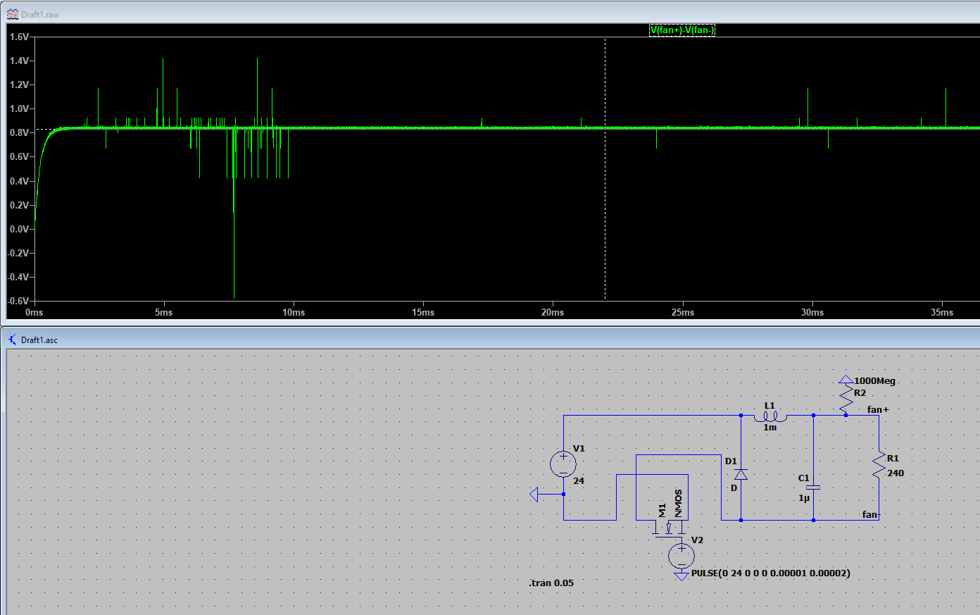
@Danal Yes, I would definitely like to see them made and sold to the general public. I will make a post about it there whenever I will get some free time.
@dc42 My bad, I guess I should have made the diagrams slightly clearer.
The 100M resistor is there because LTspice throws a "Singular matrix" error without it, since it thinks that there is a node floating. Adding the 100M resistor is a quick solution that does not affect the circuit given how large it is. I haven't saved it, and now I tried to redraw it, but for some reason I get the same error even with the 100M resistor. If I add a large resistor to every node the error goes away, but it only simulates up to a few microseconds, and then LTspice freezes.
The negative terminal of the 24 supply was grounded, there is a small blue triangle there which indicates ground.
I guess it is possible that I made an error in the simulation of the LC circuit as I am not able to run it again. I will try again later.
@arhi The additional resistor would reduce the max voltage of the fan. Wouldn't it be a good idea to add instead a resettable fast blow fuse?
Also I thought the flyback diode is only really needed for normal brushed fans, and not for brushless ones. Since the whole point of this module is to make brushless fans work better with pwm (brushed DC ones, if they exist in these sizes, would already handle PWM quite well), would a flyback diode still be needed?
I know this is a very old topic, but it is the first one that comes up on Google when searching for fixing fans that do not work with PWM, so I hope to be able to share a solution with people who need help.
I found a good and cheap solution and I made a new topic about it here.
I recently bought a few somewhat expensive fans from Digikey, and they turn out to not work well with PWM control, no matter what the speed is set to. Some fans spin at 100% up until 50% PWM, and then stop completely, or others have unpredictable speeds (going from 0 to 50% is resulting in a very different speed to going from 100% to 50%).
Pretty much all fans used in 3D printers are brushless, so they are not meant to be used with PWM control, even though a lot of them work decently with it.
For the rest of the post, I will assume a 24V Supply, since this is what I have and I think it is the most common voltage nowadays.
I came across this thread from 2 years ago exploring a fix, but the best fix they came up with was not only not effective, but actually slightly dangerous for the fan.
Using the LC filter suggested resulted in transient spikes reaching 26V, which might potentially damage some fans. Also changing the PWM ratio does not change the average voltage, so I can't see how that would affect the speed of the fan. The problem with this circuit is that the fan (modelled as a resistor), affects the filter. To fix it using only passive components we would need a very large capacitor that would cause large currents, which can damage the mosfet on board.
Instead, we will need a high impedance input from the filter, and a low impedance output to the fan. Cheapest way with the lowest amount of components is using a high power op amp wired as a voltage follower.
With a few more components, it is possible to use a more basic op amp and a mosfet as an emitter follower to achieve a higher current, but a £0.40 L272M can do 0.7A per channel and my fans only use about 0.07A on max speed at 24V, so I went for the easier option.
I played around slightly with the values for my LPF, and I came up with this as my final solution, except with a L272M as the opamp instead of the LT1677 (LTspice doesnt have it in its library). The R3 is there as a pull up resistor, so the lower node on the diagram becomes 24V when the onpoard mosfet is off, so we get a proper square wave.
The overall cost is about £2 for two channel (as a L272M is a dual opamp). I have built it and it does work very well. My cheap DSO oscilloscope can't even measure the noise, and all the fans I have tried adjust their speed smoothly from barely spinning to full speed. Also some fans that work fine with PWM, such as the Pengda blower from Trianglelab, seem to run even quieter at roughly the same airflow using the adjusted DC.
I will add photos of the scope output at a later date since I am currently printing stuff using the module.
Here is a photo of the module itself. (excuse my messy wiring)
Only very small issue is that the voltage will only go to ~0.9V lower than the output. I guess with an emitter follower circuit and a rail to rail opamp it would be possible to get closer, but in my use case this is not really noticeable and does not matter. Also of course you will have to readjust your fan profiles.
At even 10+ quantities with a custom small PCB, it would be possible to get the BOM to about £1 each. There aren't any specialised modules for this currently, so I think there's definitely a market for this. I think this might be something for Duet3D team to consider making as an addon. I got plenty of spares for all the parts that I might never use again, so if an Admin wants to test it too I can send parts to build a module for free (I'm in UK).