Mesh Calibration Issues (Duet Maestro 1.0, FW 2.02, BLTouch)
-
@classicstyle said in Mesh Calibration Issues (Duet Maestro 1.0, FW 2.02, BLTouch):
Is there a way to verify that mesh compensation is occurring? (besides it just working)?
Print an STL like this once with mesh disabled and once with it enabled. That will show how effective it is.
-
@grizewald Thanks for the clarity about m122.
I actually have been trying things most of the night and this morning. It seems like every time the wind changes direction, the corners that are above or below zero change. I'm running a dual-z hypercube with 4 12mm guides. I think I'm going to have to figure out a pilot bearing for the top of the cube to make the lead screws more stable cause they do allow the build plate to wobble some.
-
As an example, this is what my levelling mesh looks like:
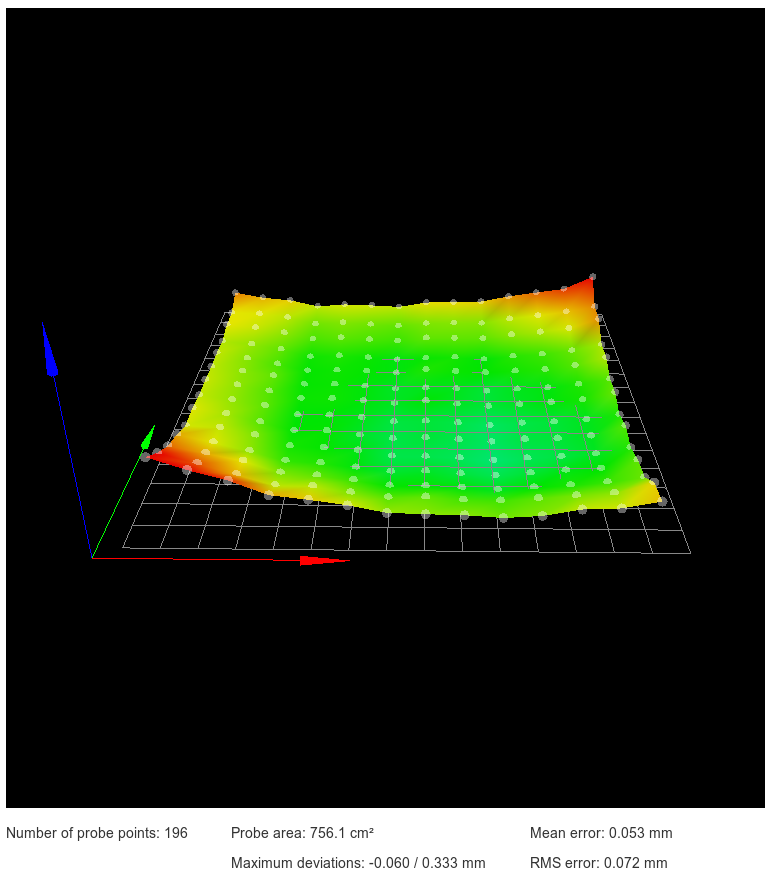
Not too pretty considering the bed is a 310mm square Anycubic Ultrabase on top of a 329mm square 3mm thick aluminium plate.
I'm considering heating it up as high as my heater will go (around 120C) to see if it might release the stress which seems to have formed after I mounted the glass plate.
I see the Hypercube uses a similar, brain dead, way of mounting the print bed as my V-Core printer. Fixing a plate at four points is just plain dumb. It should be fixed at three points in a triangle only. That way, you can adjust for roll and then adjust for pitch without ruining the first roll adjustment.
I don't know if you're using springs like I see on the Thingiverse page for the Hypercube, but I don't use springs on either of my printers. All I use is nylock nuts to fix the height and keep it fixed. My V-Core's mountings are actually free to move in certain directions to prevent any problems when the bed expands due to heating.
-
@grizewald Thanks for all the insight about 3-point mounting. Something I had definitely never realized. I actually have a Tronxy XY-2 as my first printer and went through the 4-sprung corner madness and said "no thanks, this sucks" to repeating that for my hypercube. I'm solid mounted to a 6-bar 2020 frame. Essentially it's a square frame of 4x2020 extrusion, then two 2020 extrusions are laid across the frame, resting on top of it. It's then solid mounted to the frame, and the bed is solid mounted to those two 2020s via v-nuts. I know it sounds overly complex, but I wanted a lot of adjustability while I dialed in the machine.
You reminded me that my 90 degree frame-to-2020 mounts are slotted, so I've been trying to dial that in since about 2 messages ago, starting with a simple 9-point grid to rough-in the level, then I'll up the resolution once I have all four corners roughly leveled and as close to 0.00 Z as possible. Getting closer....

For the moment I'm ignoring the middle blue points because I can actually see the swale in aluminum from where I'm sitting.
 I have a mirror on the way to hopefully help this problem long term.
 -
I don't know why it took me so long to realize I should be using my feeler gauges to level the platform.
 But here's the latest. Now that it's mostly flat, I'll worry about raising it to 0-ish tonight. Now time to start increasing resolution.

Edit: ugh, just re-homing the Z should get it to zero-ish. I'm clearly firing on all cylinders today.
-
That looks very nice indeed!
Progress at last eh?
")
-
Indeed.
I did a test print of that stl Phaedrux provided. It failed to print well directly on aluminum, but I did have M122 added to the end of the gcode. Here's the relevant portion:
Bed compensation in use: mesh
Bed probe heights: 0.000 0.000 0.000 0.000 0.000I don't understand the purpose behind the probe heights line - I only have g28 hitting Z probe at one coordinate - the middle of the print bed. Anything to be concerned about?
-
That doesn't look right. All I see if I run M122 is:
Bed compensation in use: mesh, comp offset 0.000
My Z-Probe configuration section looks like this:
; Z-Probe
M574 Z1 S2 ; Z end stop is probe at low value
M558 P8 R0.4 I1 H5 F360 T6000 ; Set Z probe type to inverted, unfiltered piezo and the dive height + speeds
G31 P500 X0 Y0 Z-0.02 ; Set Z probe trigger value, offset and trigger height
M557 X5:285 Y5:275 P14 ; Define mesh gridYour output looks like maybe it's set up to do manual probing. Hopefully someone will recognise what your output means. I'm pretty sure it's nothing to do with homing. I have one homing point which is in the middle of the bed at the same Y point as my two Z axis lead screws are mounted.
-
My Z Probe section:
; Z-Probe
M574 Z1 S2 ; Set endstops controlled by probe
M558 P9 H1.5 F120 T6000 ;A5 B1 ; Set Z probe type to bltouch and the dive height + speeds
G31 P500 X-25.3 Y0 Z0.675 ; Set Z probe trigger value, offset and trigger height
M557 X25:200 Y25:200 S20 ; Define hi-res mesh grid <-- OMG I didn't know about the "P" argument... So many maths could have been saved
;M557 X35:365 Y35:365 S330 ; Define low-res mesh grid -
@grizewald I updated my firmware to latest, that made my results look much more like yours.
Bed compensation in use: mesh, comp offset 0.000
Going to try re-printing now, even though my bed is still unlevel af.

Here's hoping. Well, here's hoping the mirror gets here soon so I can clamp it to the bed and be done with this stupidness.

-
That mesh isn't really all that bad. It's only 0.5mm difference between lowest and highest spot. The compensation should be able to take care of that easily.
-
@phaedrux I'm so frustrated cause I feel what you're saying, but nothing frigging sticks!!!
Blue painter's tape? Yup, tried it. Half the 400mm^2 bed is covered in it, and glue stick, and hair spray.
 Obviously I didn't do them all in one go, but one after another. Throw the tape away, try another round. I can barely get one line to stick, but the second the nozzle changes directions, the print lifts off the surface. I've tried print temps from 190-210, and bed temps from 45-65.
  Last resort is glass. If that doesn't work, not sure what I'm going to do.
 -
@classicstyle When I was still using PEI or glass printing surfaces, I found that artist's gouache varnish aerosol (used for coating watercolour paintings) worked really well. Alternatively, extra strength hairspray. When you use hairspray, just make sure you use a newspaper or similar to ensure none of the spray gets on your lead screws or other mechanical parts.
If you find the head rips the first layer lines off the bed, are you certain that the head is perfectly vertical? If the head is at an angle to the bed, the lowest edge of the nozzle will rip the lines of filament off in certain directions only. Even 5 degrees is enough to mess things up, particularly with the E3D nozzles which have a larger flat area surrounding the actual hole in the nozzle.
Alternatively, I've seen this happen with PLA which has absorbed too much water from the air. I think the lines actually swell slightly as the water in them boils. If you live somewhere where it is often humid, you need to take particular care that your filament doesn't absorb water. Don't believe those who say that PLA doesn't absorb significant water from the air. I've seen steam coming off wet PLA filament being extruded into thin air!
I store all my spools individually in 300 x 400mm mylar bags with a 100g pack of silica gel. When I'm printing, my spools are inside a modified PolyBox which also contains 400g of silica gel and the filament is contained in a PTFE feed line all the way from the PolyBox to the extruder.
As for bed surfaces, I use an Anycubic Ultrabase on both of my printers. It is probably one of the best inventions ever. Most plastics stick to it without any additional sprays or tape and once the print is finished and the bed cools down to under 30C, you just pick up the print. No scraping or other dangerous operations.
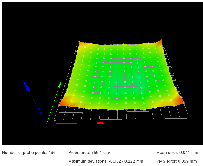
I got my bed looking a lot better after some extreme heat and a few adjustments:
-
Well, I found tonight that I am a moron. I had forgotten two X-gantry retaining screws to hold the gantry rods in place on one side. There was a non-trivial amount of torsion on the print head as a result. Wondering if that was the source of the "scraping" of the print.
Second, I'm getting closer now that my mirror arrived.

Going to try printing in a bit.
-
For the first time in 2 weeks, I made it to layer 5 on a print with no errors.
That elation tho.
Thank you guys for the help. All of the combined knowledge you guys shared should be part of a book, or wiki, or something for Duet, cause that was extremely helpful and useful. Seriously, @Phaedrux @grizewald @Veti thank you guys!
The glass combined with the solve on the X-gantry made a massive difference!
-
@classicstyle said in Mesh Calibration Issues (Duet Maestro 1.0, FW 2.02, BLTouch):
Well, I found tonight that I am a moron. I had forgotten two X-gantry retaining screws to hold the gantry rods in place on one side. There was a non-trivial amount of torsion on the print head as a result. Wondering if that was the source of the "scraping" of the print.
It sounds like you found the smoking gun!