Uneven layers
-
@Haggan90
I see you have tried a lot of options already so kinda stretching on some additional ideas:On the reprap config tool, wondered what motor current you set for the Z stepper motor.
Have read the Duet board needs backside cooling as well as driver cooling. Any chance you are having an overheating issue?
I'm a mechanical engineer and new to the Duet so total N00b with firmware - but I think the true bed leveling (G32) is for independent z motors (each with their separate driver). If your 3 Z motors are tied together to a single driver (electrically or mechanically) you should be using the bed mesh compensation. Probably not related to the issue you are having, but can improve your prints.
-
@spudaddict said in Uneven layers:
Have read the Duet board needs backside cooling as well as driver cooling. Any chance you are having an overheating issue?
You cool the stepper drivers by cooling the back of the board - the stepper driver chips have metal pads on the underside which are soldered to the PCB to allow them to transfer the heat from the chip to the PCB. The mass of little holes (thermal vias) are to help in transferring this heat to the large copper areas under each stepper driver
Cooling the back of the board is enough. The top of the chip is plastic and therefore does not help in dissipating heat from the internals.
-
@Haggan90 Your image is very interesting: in the upper part, Y layers are going outside, X inside. At the middle just below the X letter, X and Y both inside. Could you please look how it behaves at the back for those specific layers: if to inside, then at the opposite also to inside, or to outside? If to the other direction, them it would mean it is printed in correct lemgth, but simply shifted. Then I think the LM12/LM8 ball carriages may have play (or something other like bed screws) and at a Z movement the bed shifts sometimes. You could test by a spring at the opposite side at the bed, so the carriage is always running at one side on the shaft. Hope you understand what I mean....
I mean: is it (exaggerated, every color is a layer) case 1 or 2?
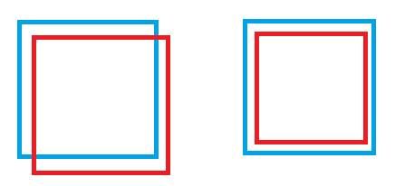
Case 1 could be a cause like above.
Case 2, it could be something like different warping because of different temperatures of the nozzle. -
Ok. I read your other thread, so case 2. I think it has to do with the temperatures, or your filament clogs the nozzle sometimes or temperature is too high (what are the black dots in your sample?).
-
One more thing you could try is setting A and B stepper to endstop position for every layer you begin, so errors like spinning/slipping gears will show up (because if you reset at each layer, the error will disappear). Maybe you have spinning gears all the time, but it shows up after long movements like at the layer changes.
-
@JoergS5 said in Uneven layers:
Ok. I read your other thread, so case 2. I think it has to do with the temperatures, or your filament clogs the nozzle sometimes or temperature is too high (what are the black dots in your sample?).
Also make sure you have run heater tuning on the bed heater and you are running it in PID mode. Running the bed heater in bang-bang mode can cause banding like that.
Duet WiFi hardware designer and firmware engineer
Please do not ask me for Duet support via PM or email, use the forum
http://www.escher3d.com, https://miscsolutions.wordpress.com -
Thanks for all the answers!
I do have independent drivers for each z axis and I do cool the underside of both the duetwifi and the duex2.I don't think it has anything to do with temperature, iv'e tried a bunch here..
It could have something to do with the Z shafts and bearings, but I can't feel any play what so ever. I use 4 16mm shafts with LMU16 bearings.
Some more photos around a new print I just did, from all angles.


-
@dc42 yeah i know, atm I don't have any heated bed and I do run PID on the nozzle.
-
This post is deleted! -
Not sure you say anywhere, it is this a coreXY printer? I’d guess there’s a loose motor pulley, just enough to shift occasionally when the perimeter direction changes, but not enough to totally slip. The diagonal shift would correlate with one loose axis on a CoreXY.
You say you’re using a reduction on X and Y, so the extra belts/pulleys may contribute to greater backlash. What belt type are you using?
Ian
Bed-slinger - Mini5+ WiFi/1LC | RRP Fisher v1 - D2 WiFi | Polargraph - D2 WiFi | TronXY X5S - 6HC/Roto | CNC router - 6HC | Tractus3D T1250 - D2 Eth
-
This post is deleted! -
@Haggan90 If it's this printer https://forum.duet3d.com/assets/uploads/files/1558767109505-155876705849450689945205442146.jpg then your white belts are with steel and may be broken.
-
@droftarts no it's using the same kinematics at the markforge printer.
-
@JoergS5 yes thats the printer, but it does not exactly lools like that atm. At first it was an IDEX printer but I changed that to try and focus on this annoying problem.. the belts on the Y axis seems fine
")
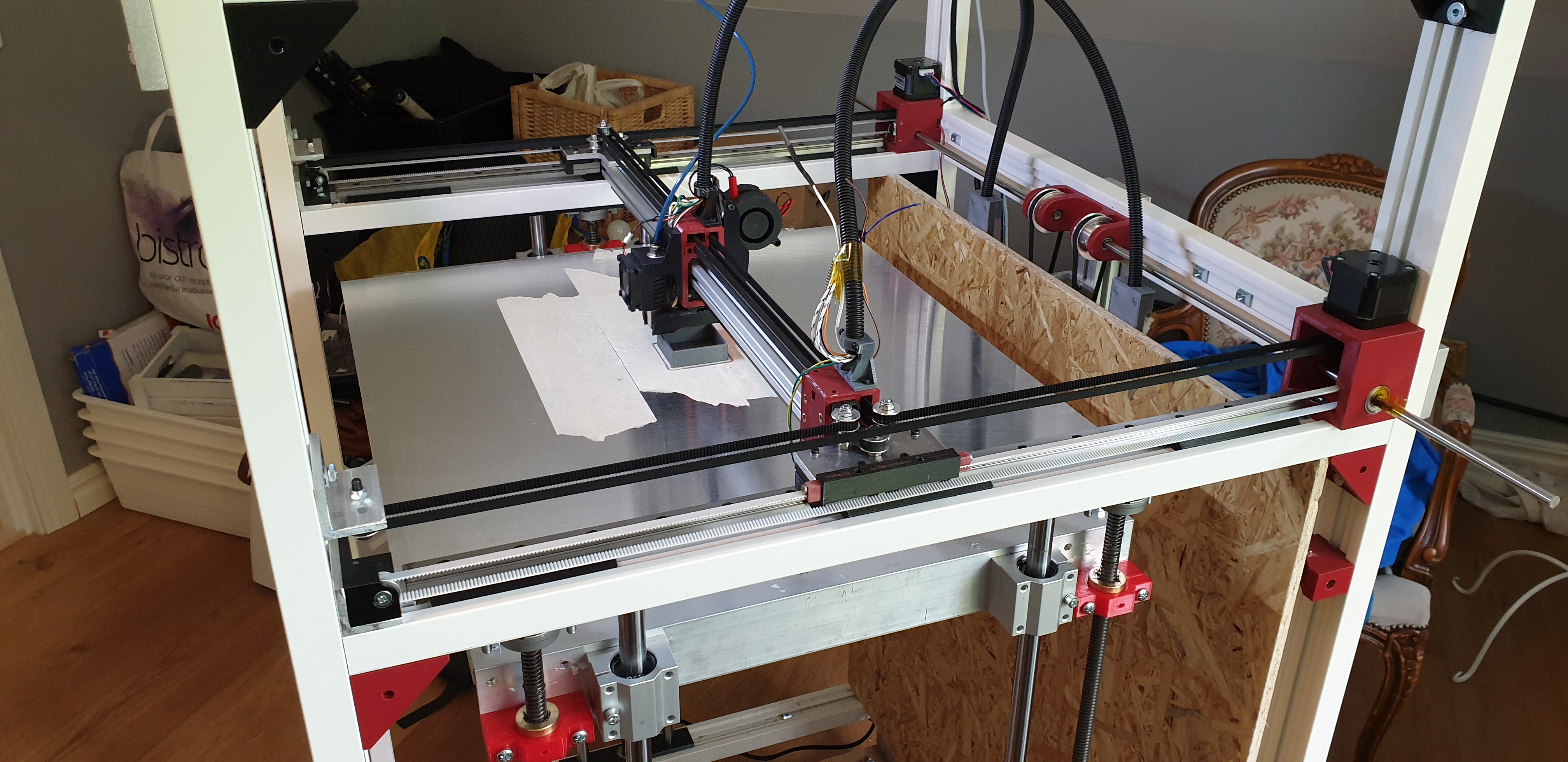
-
This is how it look right now, second picture shows the Z axis, 1 on one side and 2 on the other side.


-
@Haggan90 all your white belts with the 1 cm diameter (I mean you use pulleys with small diameter) could be broken. You will not see it, I mean the steel strings inside the belt (in the middle between teeth and back). If the other possibilities like slipping pulleys are not the reason, I would exchange them next.
In https://reprap.org/wiki/Choosing_Belts_and_Pulleys in section Belt Materials is an explanation and an image of a broken belt.
-
@JoergS5 only Z use 10mm belts, Y axis use 2 6mm belts 20t, Z has 24t
-
@Haggan90 I only wanted to give you an idea what could be wrong. I am no physicist to decide where the limit is. This will depend on the tension used also.
I think we misunderstood, with 1 cm I meant the pulley diameter, not the width of the belt.
-
@Haggan90 I have an additional idea: on the image on the right are two pulleys for the Y moves. They are not connected, right? If the Y stucks, one side will brake the movement. E. g. if thermal expansion makes X longer, the linear rails could stuck and lead to unwanted behavior. Did you fix both sides of the X Axis at the Y Axis or only one side (topic: loose and fixed bearing).
I constructed a similar mechanism for Y, but connected the 2 pulleys on the other side with a common shaft, so they cannot rotate differently.
One more thought is the 2:1 slip-sick rule: https://www.machinedesign.com/motion-control/linear-bearings-understanding-21-ratio-and-how-overcome-stick-slip-phenomenon
Maybe something like: you move Z, the LM carriage has preload and changes your overall frame, the distance of the two Y axes change and got stuck, movement is slower/faster than expected, layer is smaller or bigger.
To solve it, Mark Rehorst had an interesting approach: https://drmrehorst.blogspot.com/2018/08/corexy-mechanism-layout-and-belt.html with a moving carriage on one side of the X axis (UMMD image)
-
@JoergS5 very interesting, I will look some more into this!
The Y axis is conected, e.i one side can't move without the other. The Y motor has the shaft going through the stepper.