CoreXY movement calibration
-
I'm getting the same issue as (https://forum.duet3d.com/topic/9305/circles-eliptcal-with-fla-segments-on-the-x-direction/2) with my CoreXY printer: I get flat spots at MAX Y and MIN Y when I print circles. I thought it might be because my 'steps per mm' might not be configured correctly. After a lot of measuring and tuning I'm getting the following results on a 140mm diameter octogon:
A (diagonal): +0.01mm
B (diagonal): +0.04mm
X: +0.10mm
Y: -0.18mm
What concerns me is is that A, B, and X has small positive deviances, but Y has a larger negative deviance.
I messed with acceleration, jerk, and printing speeds - same results. I can't see any slop or binding in the mechanical system. Am I missing something? Does CoreXY also have "magical" settings?
I asked on groups on Facebook before, and the only answers I received was: "Make sure your belts are tight." I will tremendously appreciate some advice, or just somebody telling me that this is standard CoreXY behaviour.
Thanks in advance!(Sanity check: When configuring M92 X160.00 Y160.00, X and Y are the X and Y drivers for motor A that is plugged into X, and motor B that is plugged into Y. And not for X and Y movement direction. RIGHT??)
-
things to check.
when the motors are energized grab the cold hotend and see if you can move it in any direction. there should not be much play.
then check your assembly.
the belts need to be parallel to each other.
if you have a belt layout that produces triangles then the distance travelled will not correspond the the expected distance.then check for belt movements.
i.e. the belt should not move up or down on the idlers while the carriage is moving.then check the belt itself. if you use the white belts with the steel core, you could have torn those.
-
@Veti Thanks for your reply. I have done all of these checks, and:
- There is minimal play in the hotend. In our physical universe where everything is flexible to a degree, I am satisfied with the amount of play.
- All the belts are as parallel and perpendicular to each other as possible. If they are not, it will only be by fractions of a degree.
- Each belt is situated on as flat a plane as possible. I have checked and rechecked all the pulleys.
- I'm using Kevlar reinforced belts of equal lengths, tensioned by 2 pulleys on a common shaft to ensure equal tension in the belts.
I am very confident in my mechanical system, but I'm starting to doubt everything. I understand the kinematics of CoreXY (or at least I think I do), which is why I find it so strange that I have positive deviation on the A and B diagonal axes and the X axis, and negative deviation on the Y axis.
Again, thank you for your reply!
-
are you running the toothed belt side on smooth pulleys somewhere?
can you post some pictures of your printer?
-
@Veti No, toothed side of the belts are on toothed idlers, and smooth side of the belts are on smooth idlers.
Belt tensioner:
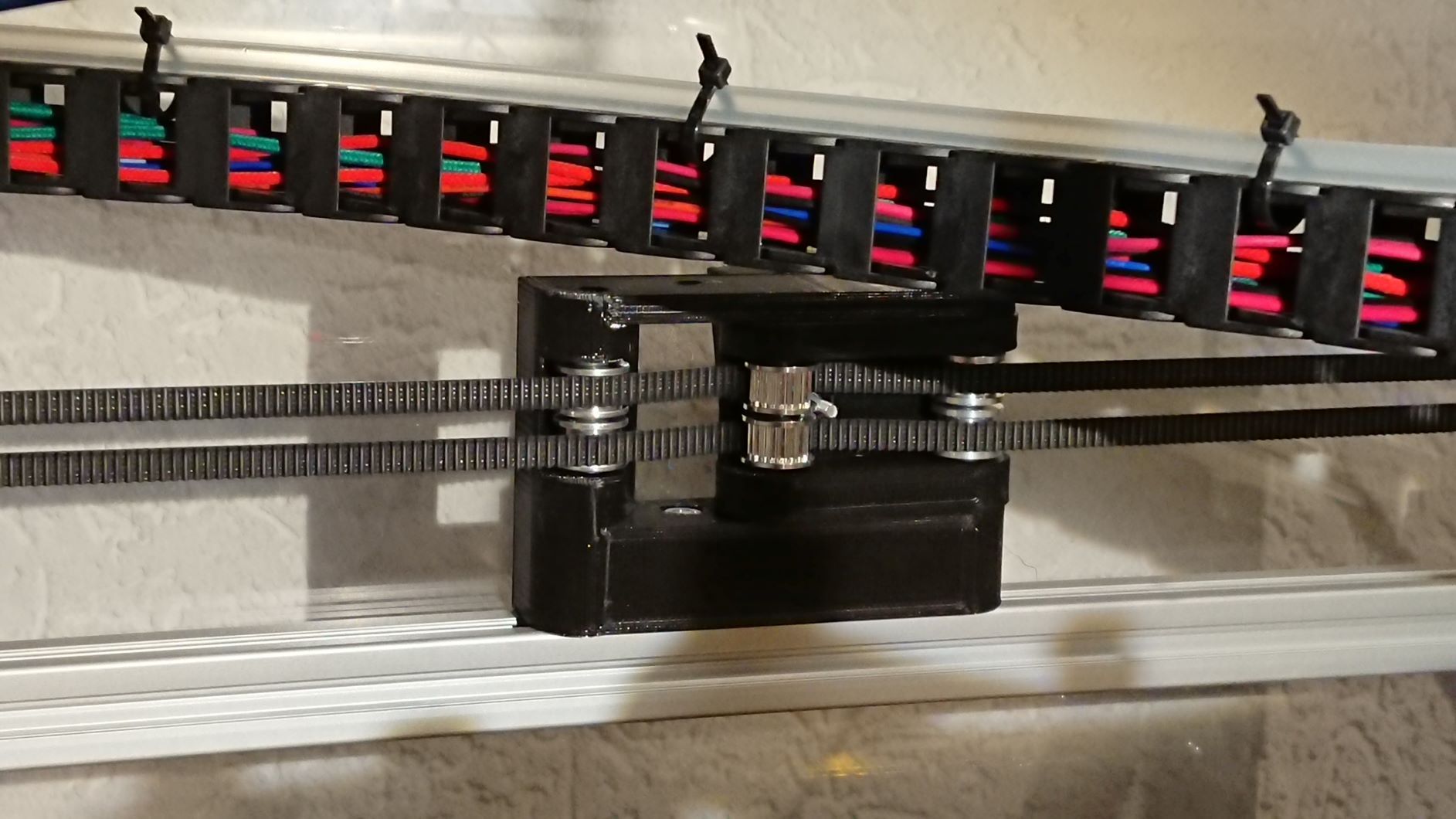
Commonly called XY joiner
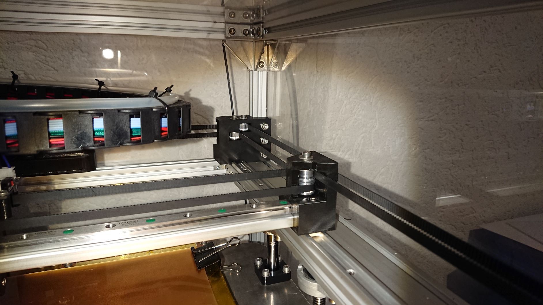
Belt alignment
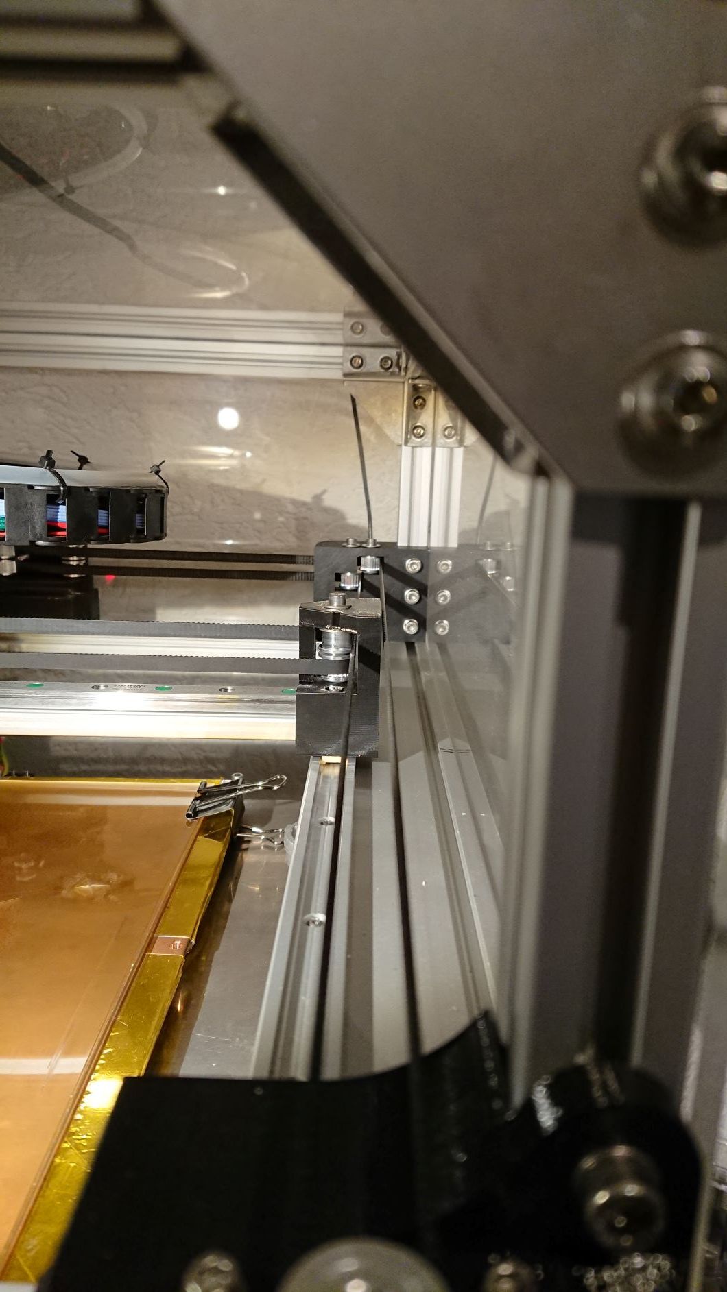
-
what kind of rails are those on the y axis?
-
An eccentric pulley, ie with bore off centre, can cause flattened circles, and positive/negative fluctuations at various points in its movement. Remove the belt, get the motor to turn as fast as it will go, and look for wobble. There’s probably a better way to test than this!
Might also be one of the idlers doing it, too. With so many on a CoreXY it’s a bit of a nightmare to test.
Ian
-
@Veti Igus low profile rails. Very smooth, very low profile. I've checked them for binding, nothing. When I've run out of options I'm going to silicone lube them, just for kicks.
@droftarts Thank you for your reply Ian. I'll have a look at that. I'm getting flat spots at the same places on circles of various diameters at different locations on the bed , would eccentric pulleys do that?
All my idlers are on seated shafts, not just on bolts, and I made sure that they all turn freely. But I did not check them for eccentricity. I am getting good repeatability on all the axes (diagonal A & B, and X & Y), just not accuracy.
Very true, all the pulleys and long belts on a CoreXY is not very ideal, but overall the 3D printing community speaks of CoreXY as if there in none better. So I built one. And now it is turning my brain into catfood. -
I am running a CoreXY printer also. I setup the Duet according to 'setting up an CoreXY machine' instructions, and so far I have round circles and square calibration cubes.
Some mumbling:
A single motor moves a diagonal axis, so I think we can exclude a loose pulley on the motor shaft, but I would check and mark them just to be sure. Grubscrews are not exactly the most reliable way of fixing a pulley to a shaft (I prefer to reinforce the joint with a drop of Loctite 603), and manually pushing the carriage around does not inflict the same kind of violence to the shaft-pulley connection as normal printer operation does.
Out of round idlers or pulleys might give a small deviation, but exactly parallel movement to X or Y requires both belts to move. If your flat spot is exactly parallel to X (you mention it happens on Ymin and Ymax), that would need two belts to move in unison. I doubt two pulleys/idlers are equally out of round.
So, some form of backlash in the Y direction seems the most logical explanation.
Assuming a bed of 100x100: You might want to home the printer, then move to the console and enter G1 X0 Y50 F6000, followed by G3 I50 F120. And watch the belts, lineair rails, etc. carefully, especially when there is a reversal of the direction. Scale the coordinates and feedrate to your bed and to what suits you.Regarding CoreXY: probably a great configuration when you have a very light moving printhead. Once adding a 'heavy' block-type lineair rail to the gantry and one or more direct-drive extruders I think a simple cartesian style stage would perform better. Two way shorter belts driving the gantry and X motor, one way shorter belt driving the printhead.
-
@DaBit said in CoreXY movement calibration:
Regarding CoreXY: probably a great configuration...
I equipped both my FT-5 and my (heavily modified) DBOT with Zesty Nimbles.
I think the CoreXY approach is clever but the FT5 was easier to get printing really well. And given that the "lower mass" advantage of the CoreXY goes away when using Nimbles, the FT5 is now on par with the CoreXY, mass wise.
Frederick
-
@DaBit said in CoreXY movement calibration:
So, some form of backlash in the Y direction seems the most logical explanation.
Assuming a bed of 100x100: You might want to home the printer, then move to the console and enter G1 X0 Y50 F6000, followed by G3 I50 F120. And watch the belts, lineair rails, etc. carefully, especially when there is a reversal of the direction. Scale the coordinates and feedrate to your bed and to what suits you.Thanks for your reply @DaBit. I'm going to try out what you've mentioned to see what it does.
@fcwilt Thanks for your reply Frederick. I have recently changed my FT-5 workhorse to Duet as well, and I suspect the same flat spot issue there too, but so far I haven't printed many round features to compare. In line with what @DaBit said, I built a CoreXY to get rid of the X motor on the regular cartesian FT-5 design. So far it has been giving me nightmares.
-
Are the "flatter" sides of the circles on opposite sides of the circles? Are they aligned with the axes or at 45 degrees?
-
@marnog said in CoreXY movement calibration:
So far it has been giving me nightmares.
I had some initial issues with the DBOT that went away when I worked to even the tension in both belts.
I wish there was a suitable tool for accurate measurement of tension in these small belts.
And I have never encountered flat spots so I have no idea what it might be.
Frederick
-
Hi,
In the other article on this type of problem dc42 said backlash was the problem.
DId you check both of your motor pulleys to insure that are securely in place?
Where else on your printer could you be having a pulley shift back and forth?
If dc42 is correct backlash suggests something is loose that should not be, and shifts when belt movement changes direction.
Frederick
-
@fcwilt said in CoreXY movement calibration:
I wish there was a suitable tool for accurate measurement of tension in these small belts
Gates carbon drive app for smart phones. Listens to the belt when you pluck it. Intended for bicycle belt drive tension, so it is a bit finicky on these smaller belts... with a little practice it will produce consistent readings.
https://apps.apple.com/us/app/bicycle-belt-tension-meter/id438346486
https://play.google.com/store/apps/details?id=com.gates.carbondrivecalculator&hl=en_US
-
@DaBit said in CoreXY movement calibration:
Regarding CoreXY: probably a great configuration when you have a very light moving printhead. Once adding a 'heavy' block-type lineair rail to the gantry and one or more direct-drive extruders I think a simple cartesian style stage would perform better. Two way shorter belts driving the gantry and X motor, one way shorter belt driving the printhead.
For info, with CoreXY, the only time that a single motor is employed is when the print head moves at exactly 45 degrees to the XY axes. For all other moves, both motors are employed. Furthermore, because of the belt arrangement, the distance a motor must turn is about 1.4x the distance of the gantry which effectively gives 1.4x the torque than one would have using Cartesian kinematics.
Those are the reasons that I elected to use CoreXY kinematics when I built my printer which has a mixing hot end with a moving mass in the Y direction of around 2Kgs. When I added a second gantry to carry the extruders and which weighs about 3Kgs, I used the same kinematics. I have demonstrated successfully printing at 300mm/sec with this arrangement and my default travel speed is always set to 350mm/sec.
-
@marnog said in CoreXY movement calibration:
Igus low profile rails.
i can not find any information regarding the stiffness of those rails.
since there are no moving parts, there needs to be a gap to allow for the movement.
this gap will decrease the positional accuracy.
does igus say that those rails are suitable for 3d printers? -
@deckingman said in CoreXY movement calibration:
For info, with CoreXY, the only time that a single motor is employed is when the print head moves at exactly 45 degrees to the XY axes. For all other moves, both motors are employed. Furthermore, because of the belt arrangement, the distance a motor must turn is about 1.4x the distance of the gantry which effectively gives 1.4x the torque than one would have using Cartesian kinematics.
Not only that, you also have two belts working which increases positioning stiffness.
My issue is not the CoreXY principle, but the combination of a large lenght of belting needed, the fairly low stiffness of the belts, and the controller sending shocks into the system. My stage uses almost 2 meters of belt for approximately 250x250mm of movement. I used the 12mm 2GT Gates stuff sold by E3D to offset the weight of my dual direct extrusion printhead, but in the first test cube I printed there was a bit of ringing visible. That was at 'only' 100mm/s with 3000mm/s^2 acceleration. Did not have that issue at those speeds with the steel-backed 10mm white belts and LinuxCNC as the controller, so the lower-stiffness belts clearly have an impact. However, take all this with a grain of salt; I did not do much tuning yet. Makes little sense when construction is not complete yet.
Your printer 'requires' two stages to move the entire printhead with the desired compromise between speed and artifacts. You are also running fairly low acceleration numbers. Probably performance is more than sufficient, but in absolute terms the performance of the stage itself is not that great. Also a sign that CoreXY is not ideal for heavy printheads IMHO.
As a comparison: my CNC-mill can move it's 125kg gantry with 500mm/s, 4000mm/s^2 acceleration with a deviation from commanded position below 8um. I can reach well above 1G acceleration with the 3Nm peak torque provided by the motors, but 500kg of machine starts walking around when I do that. True, that is a ballscrew-driven system, but it shows that stiffness of the rotary-motion-to-linear-motion converter and trajectory planning that minimizes side effects caused by finite stiffness is important. And that is CoreXY's weakness. At least with the belting we use.
OK, ballscrews, not fair. What about re-using our belts in a different configuration? If, for example, we used something like a ServoBelt linear drive / Tankdrive / whateveritiscalled, system cost would be roughly equal to CoreXY. The motors would be moving along instead of being stationary, but since stiffness is so much higher the additional moving mass would not be that much of an issue, especially not when combined with a heavy printhead.
I built the CoreXY because the principle is so elegant and I really wanted to tinker with it. But I am not convinced it is the best solution for heavy printheads. Next printer (if ever) I will try the servobelt principe. That also makes my heart tick a little faster.
-
@mrehorstdmd said in CoreXY movement calibration:
Are the "flatter" sides of the circles on opposite sides of the circles? Are they aligned with the axes or at 45 degrees?
Mark, the flatter sides are on opposite sides of the circles along the Y axis.
@fcwilt Frederick, the pulleys are properly secured to the motor shafts with grubscrews, and the grubscrews are secured with Loctite 222. And all the idler pulleys are on shafts. The flat spots look like a sure result of backlash (especially for where they are located), but I have checked, no backlash anywhere.
@Danal Thank you, I'll have a look at the carbon drive app.
@deckingman & @DaBit Because of the increased torque factor and the increase in positional stiffness is why I am having such a hard time understanding why I'm getting the inaccuracies that I'm getting. A & B axes are close to spot on, but then I'm getting the discrepancies in X & Y. Everything points to some form of backlash, which I cannot find. I'm using bowden extrusion to a single hotend. The heaviest items on the X axis is a copper heatblock and a Hiwin MGN12 rail and carriage. So it is by some distance not the heaviest setup.
@Veti Igus (or rather their reps) claims that all their products are suitable for 3D printing. Yes, there is a gap to allow movement, but the way that I have them set up (along with the CoreXY system) would result in side to side movement, and not along its direction of intended travel. I have them on the Y axis, so any backlash should be in the X axis. For more info: https://www.igus.com/product/920
-
@marnog said in CoreXY movement calibration:
claims that all their products are suitable for 3D printing...
My CoreXY machine is a modified DBOT - all wheels running of v-slot extrusions, except for the Z axis. I had my doubts but it seems to work.
So it doesn't seem likely that those rails you have are the problem but who knows.
However, if all else fails perhaps you need to replace them with typical linear rails just to be sure.
Frederick