Circuit-design Peltier Element
-
Hi. I need a little help from experienced people.
I want to control a Peltier element with a microcontroller,
with PWM. May? The peltier element has the following parameters:
Imax=8.5 A, Vmax=15.4V.Ok... I have a 12 volt source,17A for example.How can i design the circuit so that i can control the peltier element?
A link to the peltier element data sheet is:
https://eu.mouser.com/datasheet/2/433/Wakefield_Vette_Thermoelectric_Cooler_Full_Data_Sh-1501217.pdf -
if you only need to control heating or cooling you can use the bed output, or external mosfet.
-
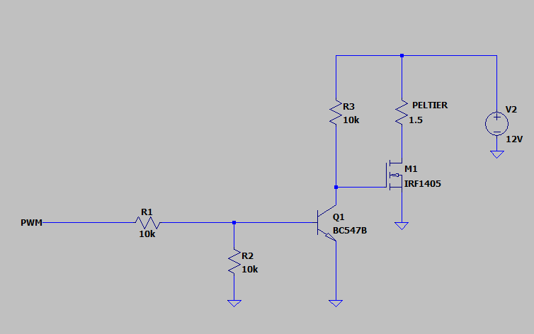
I'm using this schematic, but it's not okay. I'm not sure which series of transistors to choose and i need help for that
-
@Dani111 said in Circuit-design Peltier Element:
I'm using this schematic, but it's not okay.
A few questions
-
Do you know for sure that Peltiers respond well to PWM?
-
What voltage do you apply at the PWM input? (5V? 3.3V?)
-
Can you explain why the circuit is not OK?
-
Do you know what PWM frequency you use?
You can test the circuit with a voltmeter. Apply input voltage (e.g. 3.3V) at PWM and verify that the voltage across the Peltier is 0V. Then apply 0V at the PWM input and verify that the voltage across the Peltier is 12V.
Also, be aware that this is a negating circuit so PWM of 100% will result in 0% power and vice versa.
-
-
I forgot to mention, my peltier is TEC-40-33-127. I apply at the PWM input 3.3V and i think my circuit is not ok because the launchpad (MSP430FR4133) "scream".
-
@Dani111 said in Circuit-design Peltier Element:
i think my circuit is not ok because the launchpad (MSP430FR4133) "scream".
I see. Screaming launchpads is beyond my limited knowledge in electronics.
-
Your schematic should work for low PWM frequencies, your 'screaming', whatever that might be, is probably caused by a wiring error. Are you sure you connected the GND's of the 12V supply and the uC board together?
Other than that the circuit is suboptimal; it takes R3 a long time to charge the gate of M1 which increases dissipation. Replacing R1/R2/R3/Q1 with something like a TC4427 would be a better solution.
Regarding PWMming TEC's: you can do that as long as you keep the PWM frequency above 1kHz or so. If you PWM with a low frequency there is too much stress on the thermocouple joints due to them thermally expanding and contracting many times a second.