Ongoing Mesh Level Compensation issues
-
Re: [Mesh Calibration Issues (Duet Maestro 1.0](FW 2.02)
I finally got some time in my life to go back and continue working on my HyperCube. I designed a new x-carriage/extruder mount combo block that I'm quite happy with, and am now trying to get my printer to finally work. In the post I reference above, I got realllllllly close prior to the x-carriage breaking and wiping out a lot of my progress.
Current problem
Between X20Y20 and X20Y200, I can lay down a straight line of PLA essentially without issue. Anywhere else on my print bed, and I get no adhesion.Current Equipment
- Bowden-type hot end
- BLTouch
- Mirror glass print bed
- Lots of AquaNet!
The question
Is there some way to ensure I have mesh leveling operating correctly? It seems very odd that I am unable to get anything to adhere to glass with as flat a surface as the one attached.
I'm not even getting scraping, the bed seems too far from the head, but not everywhere, leading me to think mesh compensation isn't working.
config.g zprobe section
; Z-Probe
M574 Z1 S2 ; Set endstops controlled by probe
M558 P9 H1.5 F360 T9000 ;A5 B1 ; Set Z probe type to bltouch and the dive height + speeds
G31 P500 X10 Y-25.3 Z0.40 ; Set Z probe trigger value, offset and trigger height
M557 X20:320 Y20:320 P8 ; Define hi-res mesh gridOpen to thoughts, please!
-
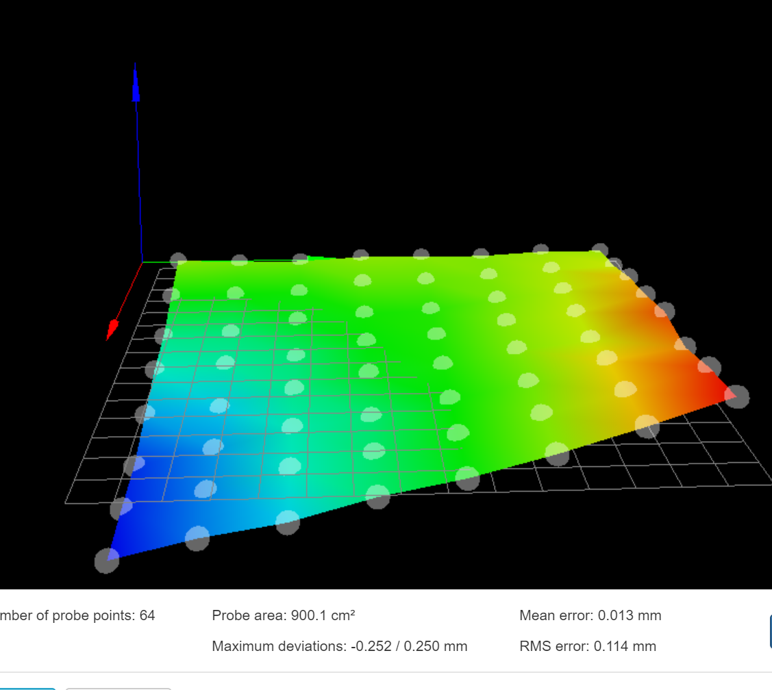
@ClassicStyle When the bed shape is like that, ie twisted along one axis, it's a 'tramming' issue. It means that one side of one axis, in this case the Y axis, is not level with the other side. As you have a CoreXY, and assuming your bed is perfectly flat, it means that the top rails of your frame are not level with each other, so the nozzle is moving vertically up and down as the axis moves horizontally.
You can probably test this visually; Move the nozzle from the origin along the Y axis, and it should maintain the same height, while moving it along the Y axis as X maximum will make it look like it is rising and falling.
It is only 0.5mm out, so not much; the mesh view makes it look far worse! But it will be enough that large objects won't stick. You may find it's the surface you have put the printer on is not flat, or the frame (which is a cube, so can distort) is very slightly out of square. Simply supporting one corner of the machine may be enough to resolve this, or having adjustable feet. If the frame is very firmly bolted together and doesn't have any flex in it, you may have to undo some rails to adjust.
While the firmware can use compensation to account for this (and it should be working), I prefer getting my printers as mechanically square as possible, rather than have the extra overhead/complexity of the firmware compensation, and the effect it has on printed parts, which is minor, unless you're trying to print to a very tight tolerance.
Ian
Bed-slinger - Mini5+ WiFi/1LC | RRP Fisher v1 - D2 WiFi | Polargraph - D2 WiFi | TronXY X5S - 6HC/Roto | CNC router - 6HC | Tractus3D T1250 - D2 Eth
-
did you add the enable mesh leveling to you start gcode?
G29 S1 ;enable mesh compensation -
For bltouch its recommended to use trigger value of 25 instead of 500. So in G31 command put P25 instead of P500
-
@droftarts Thanks for the notes. I realize it's possible for my machine to need tramming, just not sure how I can get 0.5mm of accuracy on any tools I have, when I do not have a fixed frame of reference to measure against. I'll investigate though.
@greenlee Didn't know about G29. Adding it to my print start g code in cura.
@aidar Cool tip, I've updated this value and will report back.
-
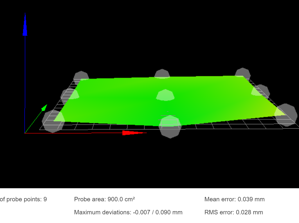
bed is much more level, but same symptoms.
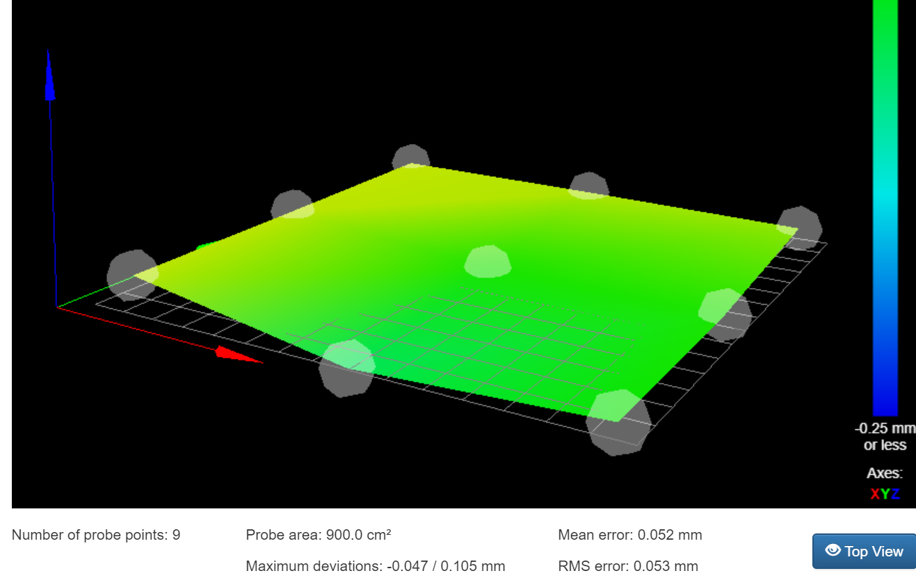
Simplified the sample size just to be able to iterate faster. The 380 X,0 Y corner is still a bit out, but overall much better. Still no adhesion at anywhere other than the 0,0 corner.
-
ugh.....
still no adhesion.
Mirror surface with aquanet. I simply do not understand wth is going on.
I'm trying to print in the center of the bed, but nothing sticks.
For ref:
known-good PLA @200C
Mirror bed with Aquanet at room temp (works on my TronXY XY-2 no problem)
Layer height 0.12mm
Initial layer at 0.12mm
0.4mm head
print volume is 380^3 -
9 points for an area of 900cm² is not enough if the area is not perfectly flat
-
buahahaha!
Resolved with the info on the following page.
https://duet3d.dozuki.com/Wiki/Bed_levelling_using_multiple_independent_Z_motors#Section_Example_for_2_motorsThat made everything work like butter. Yes, tramming was the major issue. I'm no longer even using mesh compensation, just the z-screw leveling. Immediate improvement and adhesion. Now I just need to make sure I'm actually at proper nozzle height, since I appear to be scraping off levels with my nozzle.
Thanks for the tips all.
-
I recommend, after you apply mesh compensation by G29 S1, move your printhead to lowest point on bed (witch is about center in your case) and do one more single probe by G30. If its still doesnt stick, increase your trigger height little by little, say 0.02 at times and try again until you find value that works for you.
-
@Veti I was only using the 9 points as a quick sanity check for corners (since that's my only manual adjustment points). Not intending to stick with 9 when actually printing. But thanks for the heads up.
-
Hello,
On my delta I have similar issues. Recently upgraded to a duet wifi and a smart effector. All works nice, except I cannot get a decent first layer. Mesh compensation is enabled in the web interface (I do not have extra code for this in the g-code). Leveling works nice, I set it to probe each point max 3 times with a maximun error of 0.02mm (smaller fails). Bed is heated up before probing, and no homing after probing in case of any errors there.
The level picture looks consistent every time. also with a simple paper test it seems in the ball park.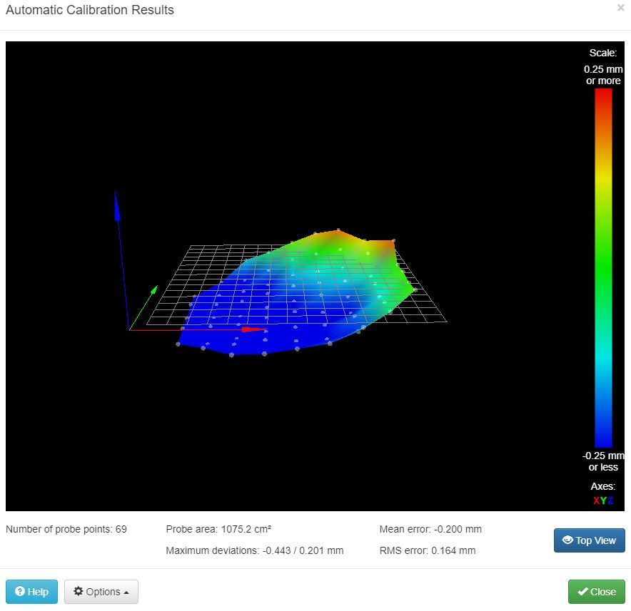
first layer thickness is 0.15 At some points it is scraping the bed, and some points it is not sticking. This varies over a short bit of the bed.
The bed level is maybe not great, but even the old anycubic board dealt with it better.
It is an anycubic predator by the way, with smart effector and magball arms.

This is my best result so far... -
The bed height map shouldn't have that tilt if your machine has been calibrated. When you run auto calibration, how many factors are you using (the S parameter in the final G30 command in bed.g), and what deviation is reported?
-
S6 is the parameter in the final G30 command.
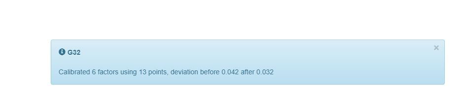
Not sure what it does with this and what the difference is between the mesh grid compensation. I did try both, but not to much result. -
Ok, RTFM. so I did an autocalibration and put those values in the config.g
After that this height map is the result:
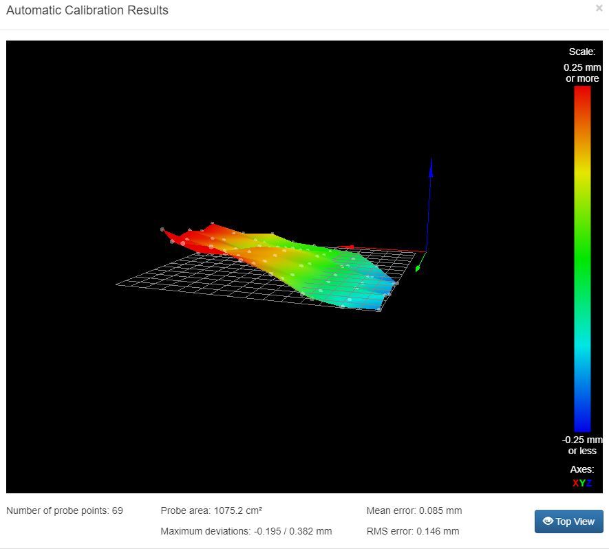
The tilt is still there, tried it twice with the same result. Also the printing gives the same first layer with the highs and lows in the same place... -
@Lakeman Perhaps you should start a new thread with your issue. Include the details of your own machine, include you config files, etc.