Z axis off, Layers to tall.....
-
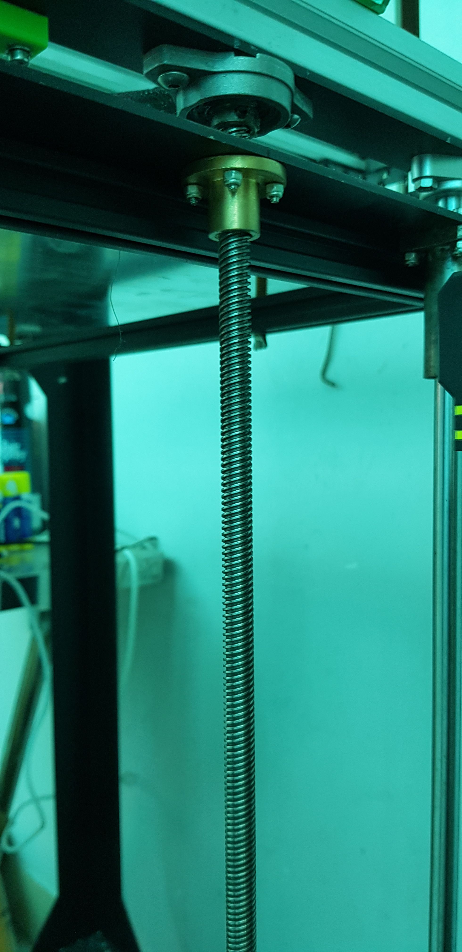
@dingo007 Some details of your machine might be useful! Is it a commercial machine you're converting, or building yourself? Are Z motors 1.8º (200 steps per rotation) or 0.9º (400 steps per rotation)? What does the Z leadscrew look like?
There's a leadscrew calculator built in to the RepRapFirmware configurator on the motors page https://configtool.reprapfirmware.org/ or use the Prusa one https://blog.prusaprinters.org/calculator/#stepspermmleadIan
-
@droftarts in Marlin it was set as below. The machine is home built, not commercial branded, the Z motors are 1.8 the Z screw looks like a normal z screw, nothing odd.
/**
- Default Axis Steps Per Unit (steps/mm)
- Override with M92
-
X, Y, Z, E0 [, E1[, E2...]]
*/
#define DEFAULT_AXIS_STEPS_PER_UNIT { 160, 160, 1600, 185 } -
They are based on the pitch of the lead screw.
So if you haven't changed something at the drive the values doesn't change.
Maybe there is to much friction....To calculate you can use the online config tool.
https://configtool.reprapfirmware.org/
In the motor tab click into the value of steps per mm.
-
@dingo007 said in Z axis off, Layers to tall.....:
@droftarts in Marlin it was set as below. The machine is home built, not commercial branded, the Z motors are 1.8 the Z screw looks like a normal z screw, nothing odd.
/**
Default Axis Steps Per Unit (steps/mm)
Override with M92
X, Y, Z, E0 [, E1[, E2...]]
**/
#define DEFAULT_AXIS_STEPS_PER_UNIT { 160, 160, 1600, 185 }What was the microstepping in Marlin? You halved the X and Y steps per mm. The pitch of the thread on the Z screw is the important thing, saying "the Z screw looks like a normal z screw, nothing odd" doesn't help define what it is at all; there's a huge range. If you don't know, post a picture.
Ian
-
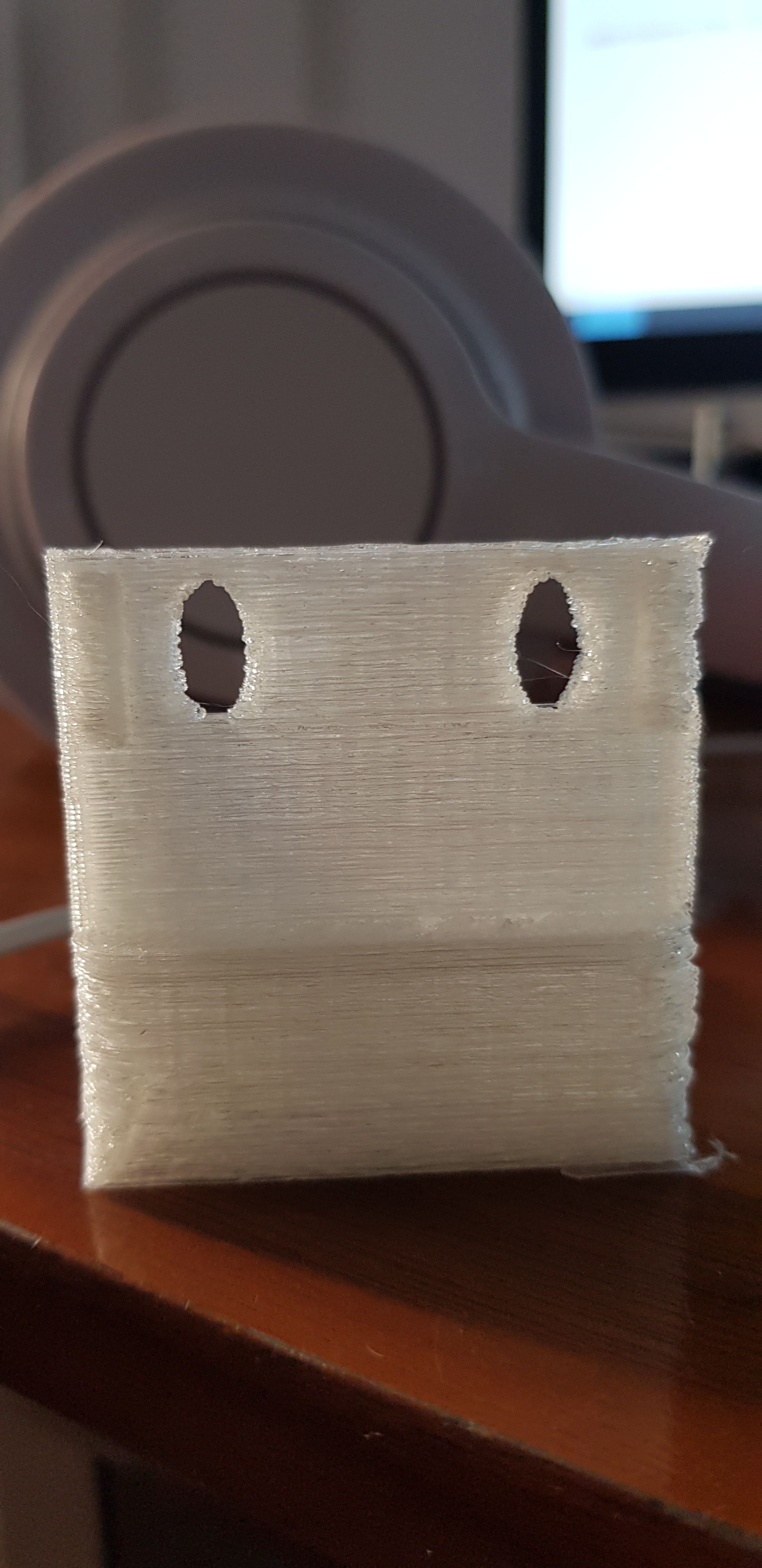
@droftarts sorry i dont see any microsteppings in marlin config.... ! ive uploaded a photo, also i note, i measured the with of the circle printed it was 4.5, the length top/bottom of the elonagted side was 9, so im just guessing here that i need to cut my step in half somehow, now trying to narrow down the screw i have looking at RR config the only one that makes sense with new steps of 800 is trapezoid
 image url)
 -
@dingo007 said in Z axis off, Layers to tall.....:
4.5, the length top/bottom of the elonagted side was 9
Strange.. I was thinking about some tenth....
-
@DIY-O-Sphere nope, i can assure you its way out.... X and Y seem fine.... but Z is definitly off

-
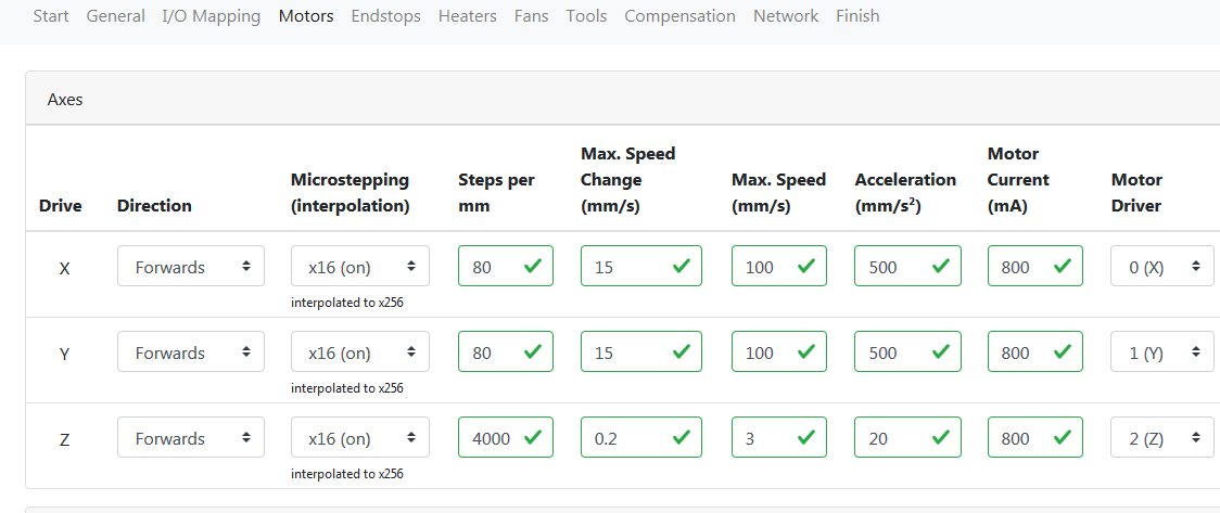
So I think Ive nailed it, taking a guess at editing the Z steps... measuring the width says 4.5mm however circle height was 9... by my calculation that says i am 100% over stepping, playing with the variables in RR config and not knowing the screw pitch, i can determine that Trapezoid TR4 gives my the exact 800 number which is 50% of the 1600 it was originally set at. So i reset it to 800, and printed a 20x20x20 XYZ test cube... and it came out as perfect 20x20x20.... so looks like i nailed it and my Z screws are Trapezoid TR4. So consider this fixed.... now onto adding my second Z end stop.
; Drives
M569 P0 S0 ; physical drive 0 goes forwards
M569 P2 S1 ; physical drive 2 goes forwards
M569 P1 S1 ; physical drive 1 goes forwards
M569 P3 S0 ; physical drive 3 goes forwards
M569 P4 S0 ; physical drive 4 goes forwards
M584 X0 Y2 Z1:4 E3 ; set drive mapping
M350 X16 Y16 Z16 E16 I1 ; configure microstepping with interpolation
M92 X80.00 Y80.00 Z800.00 E420.00 ; set steps per mm
M566 X900.00 Y900.00 Z12.00 E120.00 ; set maximum instantaneous speed changes (mm/min)
M203 X6000.00 Y6000.00 Z180.00 E1200.00 ; set maximum speeds (mm/min)
M201 X500.00 Y500.00 Z20.00 E250.00 ; set accelerations (mm/s^2)
M906 X800 Y800 Z800 E800 I80 ; set motor currents (mA) and motor idle factor in per cent
M84 S30 ; Set idle timeout -
@dingo007 said in Z axis off, Layers to tall.....:
So consider this fixed.... now onto adding my second Z end stop.
before you do please read
https://duet3d.dozuki.com/Wiki/Bed_levelling_using_multiple_independent_Z_motorsthat is a better and easier solution
-
@Veti thanks, ive read the document, though i dont see alot of information about dual Z endstops also
theres also this so im still a bit confused
https://duet3d.dozuki.com/Guide/Independent+Z+motors+and+endstop+switches/18 -
@dingo007 said in Z axis off, Layers to tall.....:
though i dont see alot of information about dual Z endstops also
the point is that you dont really need dual z endstop.
the bed is probed and the height is adjusted to truely level the bed.if you really want dual z endstop you should update to rrf3
see
https://duet3d.dozuki.com/Wiki/Gcode#Section_M574_RepRapFirmware_Num_3 -
... how does a single end stop provide a truey level bed.... it cant, it requires 2+ to level both sides.... as for using RR3 id like to once i get it all configured properly... and i looked at rr config for 3 and it doesnt appear to function.
-
@dingo007 said in Z axis off, Layers to tall.....:
how does a single end stop provide a truey level bed.
not by using an endstop, but a probe.
the dual endstop feature is only really supported in rrf3
there is a workaround in rrf2 by splitting the axis up during homing, but there is no point setting that up anymore in my opinion.