@dingo007 Yupp thats resolved now... all motors working
Best posts made by dingo007
-
RE: Duet II Ethernet steppers not movingposted in Duet Hardware and wiring
-
RE: Duet 3 XYZ Optical End Stops configurationposted in General Discussion
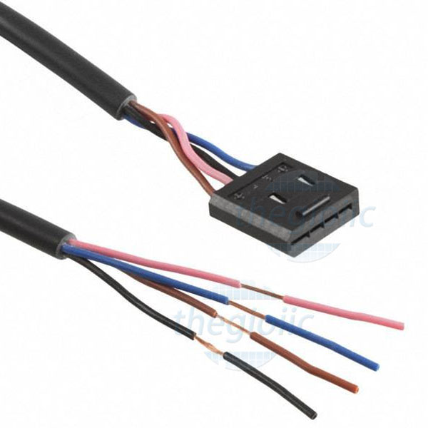
so to update all.... i have a new cable and end stop on the way... and yet what do i find....
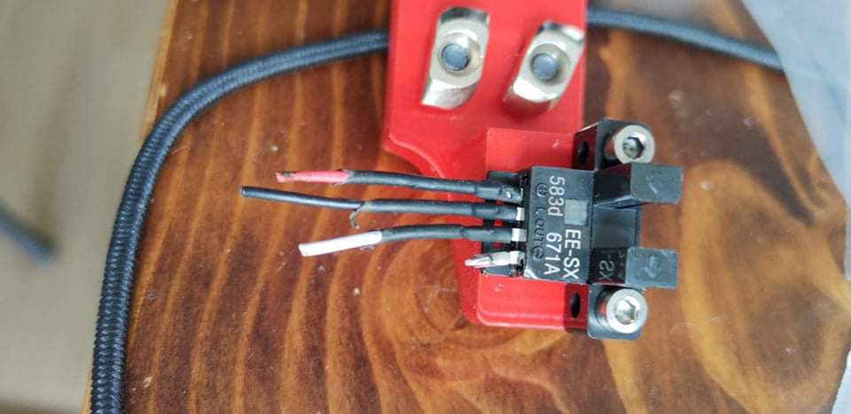
the simplest of mistakes by reversing black and white wires by the builder, I chase issues for 2 days.
-
RE: Duet rejected the HTTP requestposted in Duet Web Control
Bingo... that worked, have GUI now Thanks
-
RE: Duet 3 XYZ Optical End Stops configurationposted in General Discussion
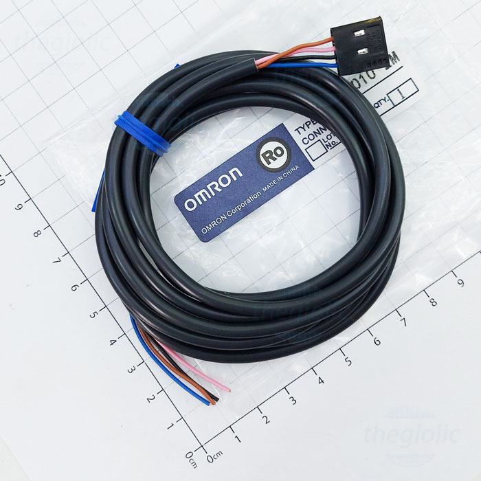
@fcwilt i have the proper omron cables being delivered tomorrow, no idea why they solder these ends.
-
RE: Duet 3 XYZ Optical End Stops configurationposted in General Discussion
@dingo007 and this is fixed now, XYZ all home correctly now,
thanks for the config hint
")
; Endstops
; ****************************************************************************************************
; end stops
; -- X,Y,Z,etc = location of endstop (0 = none, 1 = low end, 2 = high end)
; -- S = type (1 = switch, 2 = probe, 3 = motor stall (one), 4 = motor stall (multiple)
; -- ! = invert ^ = enable pull-up
; ****************************************************************************************************M574 X1 S1 P"!io0.in"
M574 Y1 S1 P"!io1.in"
M574 Z1 S2 P"io7.in"; Z-Probe
M950 S0 C"io7.out" ; create servo pin 0 for BLTouch
M558 P9 C"io7.in" H5 F120 T6000 ; set Z probe type to bltouch and the dive height + speeds
G31 P500 X0 Y0 Z2.5 ; set Z probe trigger value, offset and trigger height
M557 X15:215 Y15:195 S20 ; define mesh grid
Latest posts made by dingo007
-
RE: HEVO triple kinematic bed configurationposted in General Discussion
ok and this is compared to the machine home position X0Y0 including the probe offset ?? so im measuring from that point to the pivots i take it.
-
RE: HEVO triple kinematic bed configurationposted in General Discussion
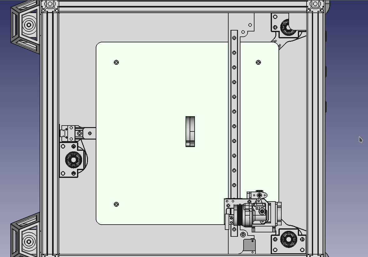
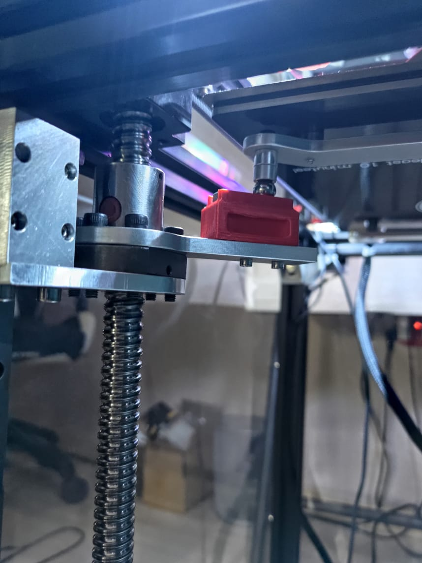
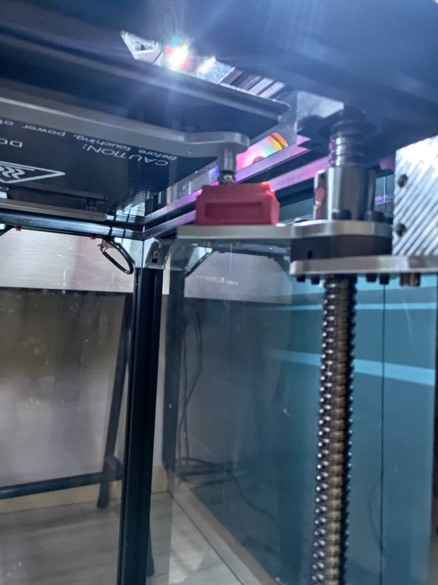
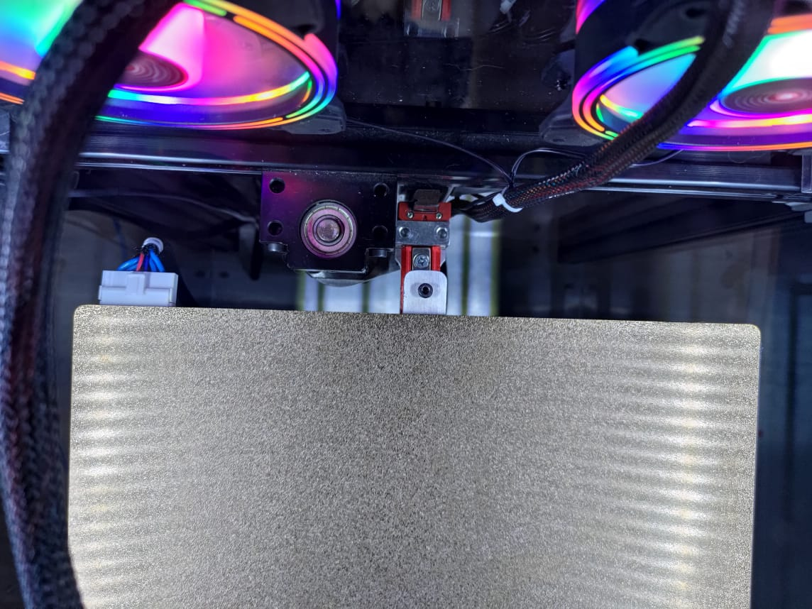
ok here is the top and bottom side cad of the bed, plus the photos of it above, im literally not sure what/where to measure. Am I measuring at the screws, or the ball studs, which align under the board and offset slightly with a bracket, am i measuring at the screws, or the ball studs, also do i include the offset from the board to the ball stud? and you will also notice on the rear screw it has a mount from the Z rail with a ball screw, the board sits on it centered.
for M671 ... I tried the below thinking i would measure at the ball screws, yet when i run the G32 leveling the right and read go way out of whack.
; Screws
M671 X20:125:230 Y20:280:20 S4.5 ; leadscrews at rear left, front middle and rear rightand in bed.g
G30 P0 X20 Y20 Z-99999 ; probe near a ball stud
G30 P1 X125 Y280 Z-99999 ; probe near a ballstud
G30 P2 X230 Y20 Z-99999 S3 ; probe near a ballstud and calibrate 3 motors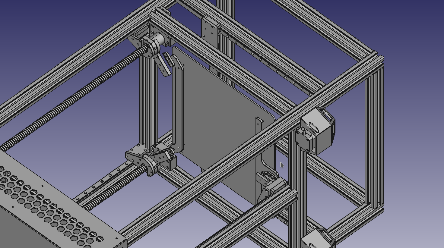
-
RE: HEVO triple kinematic bed configurationposted in General Discussion
@fcwilt
G32
Leadscrew adjustments made: 0.167 0.270 -0.504, points used 3, (mean, deviation) before (-0.022, 0.343) after (0.000, 0.000)mmm think i nailed it now...
-
RE: HEVO triple kinematic bed configurationposted in General Discussion
I removed the G29 And still thats whats giving me the error, so im not sure im measuring the probe points right. is it where the physical screws actually are? or where the ball mounts are under the board??
G32
Error: Some computed corrections exceed configured limit of 0.50mm: 0.026 3.362 -1.291config.g
; Configuration file for Duet 3 (firmware version 3.3)
; executed by the firmware on start-up
;
; generated by RepRapFirmware Configuration Tool v3.3.10 on Tue Nov 30 2021 22:33:03 GMT+0700 (Indochina Time); General preferences
G90 ; send absolute coordinates...
M83 ; ...but relative extruder moves
M550 P"300" ; set printer name
M669 K1 ; select CoreXY mode; Network
M552 P0.0.0.0 S1 ; enable network and acquire dynamic address via DHCP
M586 P0 S1 ; enable HTTP
M586 P1 S0 ; disable FTP
M586 P2 S0 ; disable Telnet ; Set idle timeout; Drives
M569 P0.0 S1 ; physical drive 0.0 goes forwards
M569 P0.1 S1 ; physical drive 0.1 goes forwards
M569 P0.2 S1 ; physical drive 0.2 goes forwards
M569 P0.3 S0 ; physical drive 0.3 goes forwards
M569 P0.4 S0 ; physical drive 0.4 goes forwards
M569 P0.5 S1 ; physical drive 0.5 goes forwards
M584 X0.4 Y0.3 Z0.0:0.1:0.2 E0.5 ; set drive mapping
M350 X16 Y16 Z116:16:16 E16 I1 ; configure microstepping with interpolation
M92 X80.00 Y80.00 Z1280.00:1280.00:1280.00 E420.00 ; set steps per mm
M566 X900.00 Y900.00 Z60.00:60:60 E120.00 ; set maximum instantaneous speed changes (mm/min)
M203 X6000.00 Y6000.00 Z180.00:180.00:180.00 E1200.00 ; set maximum speeds (mm/min)
M201 X500.00 Y500.00 Z20.00:20.00:20.00 E250.00 ; set accelerations (mm/s^2)
M906 X800 Y800 Z800:800:800 E800 I30 ; set motor currents (mA) and motor idle factor in per cent
M84 S30 ; Set idle timeout; Screws
M671 X20:125:230 Y20:300:20 S0.5 ; leadscrews at rear left, front middle and rear right; Axis Limits
M208 X0 Y0 Z0 S1 ; set axis minima
M208 X250 Y320 Z480 S0 ; set axis maximabed.g
; bed.g
; called to perform automatic bed compensation via G32
;
; generated by RepRapFirmware Configuration Tool v3.3.10 on Tue Nov 30 2021 22:33:03 GMT+0700 (Indochina Time)
M561 ; clear any bed transform
;G29 ; probe the bed and enable compensationG28 ; home
G30 P0 X20 Y20 Z-99999 ; probe near a leadscrew
G30 P1 X125 Y300 Z-99999 ; probe near a leadscrew
G30 P2 X230 Y20 Z-99999 S3 ; probe near a leadscrew and calibrate 3 motors -
RE: HEVO triple kinematic bed configurationposted in General Discussion
3 Z Screws will ball mounts at X:Y 20:20, 125:290 and 230:20
So Im pretty sure im not understanding the M671 Logic i read in that guide. Ive tried from the guide however12/3/2021, 7:35:22 AM Error: Some computed corrections exceed configured limit of 0.50mm: 2.467 -0.039 0.029
12/3/2021, 7:34:42 AM G32
110 points probed, min error -1.395, max error 2.579, mean 0.493, deviation 0.962
Height map saved to file 0:/sys/heightmap.csvconfig.g
; Drives
M569 P0.0 S1 ; physical drive 0.0 goes forwards
M569 P0.1 S1 ; physical drive 0.1 goes forwards
M569 P0.2 S1 ; physical drive 0.2 goes forwards
M569 P0.3 S0 ; physical drive 0.3 goes forwards
M569 P0.4 S0 ; physical drive 0.4 goes forwards
M569 P0.5 S1 ; physical drive 0.5 goes forwards
M584 X0.4 Y0.3 Z0.0:0.1:0.2 E0.5 ; set drive mapping
M350 X16 Y16 Z116:16:16 E16 I1 ; configure microstepping with interpolation
M92 X80.00 Y80.00 Z1280.00:1280.00:1280.00 E420.00 ; set steps per mm
M566 X900.00 Y900.00 Z60.00:60:60 E120.00 ; set maximum instantaneous speed changes (mm/min)
M203 X6000.00 Y6000.00 Z180.00:180.00:180.00 E1200.00 ; set maximum speeds (mm/min)
M201 X500.00 Y500.00 Z20.00:20.00:20.00 E250.00 ; set accelerations (mm/s^2)
M906 X800 Y800 Z800:800:800 E800 I30 ; set motor currents (mA) and motor idle factor in per cent
M84 S30 ; Set idle timeout; Screws
M671 X20:20:230 Y190:10:125 S0.5 ; leadscrews at rear left, front middle and rear rightconfig-overide.g
; config-override.g file generated in response to M500 at 2021-12-02 20:40
; This is a system-generated file - do not edit
; Heater model parameters
M307 H0 R0.206 C393.800:393.800 D2.19 S1.00 V23.3 B0 I0
M307 H1 R1.679 C247.000:247.000 D7.08 S1.00 V23.7 B0 I0
; Workplace coordinates
G10 L2 P1 X0.00 Y0.00 Z0.00
G10 L2 P2 X0.00 Y0.00 Z0.00
G10 L2 P3 X0.00 Y0.00 Z0.00
G10 L2 P4 X0.00 Y0.00 Z0.00
G10 L2 P5 X0.00 Y0.00 Z0.00
G10 L2 P6 X0.00 Y0.00 Z0.00
G10 L2 P7 X0.00 Y0.00 Z0.00
G10 L2 P8 X0.00 Y0.00 Z0.00
G10 L2 P9 X0.00 Y0.00 Z0.00and bed.g
; bed.g
; called to perform automatic bed compensation via G32
;
; generated by RepRapFirmware Configuration Tool v3.3.10 on Tue Nov 30 2021 22:33:03 GMT+0700 (Indochina Time)
M561 ; clear any bed transform
G29 ; probe the bed and enable compensationG28 ; home
G30 P0 X20 Y20 Z-99999 ; probe near a leadscrew
G30 P1 X125 Y290 Z-99999 ; probe near a leadscrew
G30 P2 X230 Y20 Z-99999 S3 ; probe near a leadscrew and calibrate 3 motors -
RE: HEVO triple kinematic bed configurationposted in General Discussion
great are those cordinate defined as where the lead screw physically is, or where it mounts to the bed, as there are ball screws under the hot bed, these are extended a bit inwards by the mount from the lead screws, basically we followed the HEVO triple Z axis design, tough its modified a bit.
Front Left
Center rear
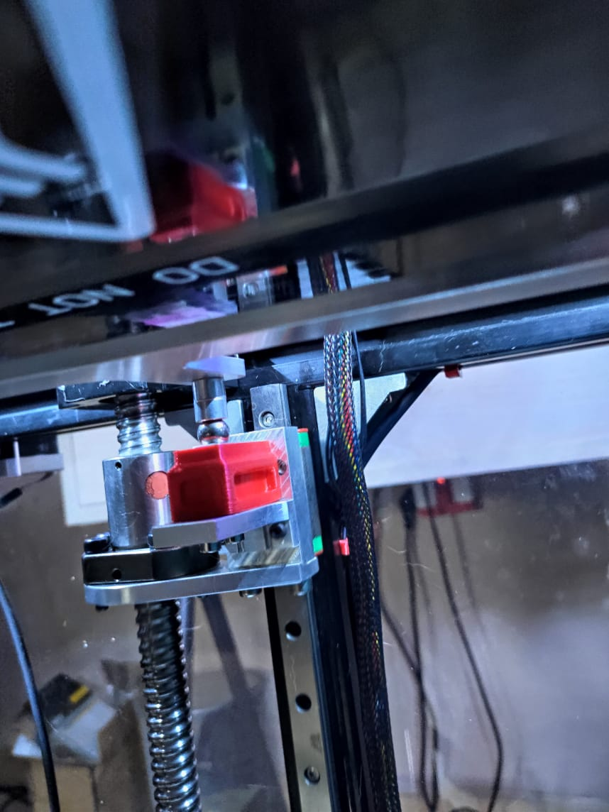
However notice the screw is offset and the rear is actually mounted at the rail
ill look around for an example bed.g
-
RE: Duet 3 XYZ Optical End Stops configurationposted in General Discussion
@dingo007 and this is fixed now, XYZ all home correctly now,
thanks for the config hint
; Endstops
; ****************************************************************************************************
; end stops
; -- X,Y,Z,etc = location of endstop (0 = none, 1 = low end, 2 = high end)
; -- S = type (1 = switch, 2 = probe, 3 = motor stall (one), 4 = motor stall (multiple)
; -- ! = invert ^ = enable pull-up
; ****************************************************************************************************M574 X1 S1 P"!io0.in"
M574 Y1 S1 P"!io1.in"
M574 Z1 S2 P"io7.in"; Z-Probe
M950 S0 C"io7.out" ; create servo pin 0 for BLTouch
M558 P9 C"io7.in" H5 F120 T6000 ; set Z probe type to bltouch and the dive height + speeds
G31 P500 X0 Y0 Z2.5 ; set Z probe trigger value, offset and trigger height
M557 X15:215 Y15:195 S20 ; define mesh grid -
RE: HEVO triple kinematic bed configurationposted in General Discussion
i have a 300x300 triple Z scew... and a BLTouch, no endstops on Z with a Duet3 board... think you can take a crack at it getting a config done for levelling
right now
; Drives
M569 P0.0 S1 ; physical drive 0.0 goes forwards
M569 P0.1 S1 ; physical drive 0.1 goes forwards
M569 P0.2 S1 ; physical drive 0.2 goes forwards
M569 P0.3 S0 ; physical drive 0.3 goes forwards
M569 P0.4 S0 ; physical drive 0.4 goes forwards
M569 P0.5 S1 ; physical drive 0.5 goes forwards
M584 X0.4 Y0.3 Z0.0:0.1:0.2 E0.5 ; set drive mapping
M350 X16 Y16 Z16:16:16 E16 I1 ; configure microstepping with interpolation
M92 X80.00 Y80.00 Z400.00:400.00:400.00 E420.00 ; set steps per mm
M566 X900.00 Y900.00 Z60.00:60:60 E120.00 ; set maximum instantaneous speed changes (mm/min)
M203 X6000.00 Y6000.00 Z180.00:180.00:180.00 E1200.00 ; set maximum speeds (mm/min)
M201 X500.00 Y500.00 Z20.00:20.00:20.00 E250.00 ; set accelerations (mm/s^2)
M906 X800 Y800 Z800:800:800 E800 I30 ; set motor currents (mA) and motor idle factor in per cent
M84 S30 ; Set idle timeout; Axis Limits
M208 X0 Y0 Z0 S1 ; set axis minima
M208 X300 Y300 Z350 S0 ; set axis maxima -
RE: HEVO triple kinematic bed configurationposted in General Discussion
ok whats your configuration look like, ill never accomplish this without help
-
RE: HEVO triple kinematic bed configurationposted in General Discussion
nice vid, im not using endstops on Z though, just the bltouch, still trying to figure out the whole configuration