Fixing a slippery magnetic bed?
-
Could you drill the thin steel sheet and aluminium to insert some locating pins? Say a 2mm diameter dowel in each corner just protruding up enough from the aluminium to go through a matching hole in the steel. Or even around the edge of the steel sheet if it's narrower than the aluminium.
BLV MGN Cube w/Hemera, K8200, Sunlu S8
-
Deliberately scratching the surfaces of the steel and aluminium with coarse sandpaper increases friction somewhat. Might be enough.
Locating pins? 2 blind holes in the aluminium, through holes in the PEI/steel, insert a dowel pin. Might not work too well due to the different thermal expansion ratio of the aluminium and steel.
If the aluminium and steel are exactly the same size a 'finger' mounted to each side of the alumium that protrudes 2mm above the surface of the aluminium might work.
-
@Nxt-1 Another alternative might be to try different magnets. The flux density of all magnets reduces as temperature increases and Ferrite are amongst the worse in that respect. Depending on the grade, it could be as much as 0.4% per degC. So if you run the bed at 50 Deg C, the magnets would lose 20% of their holding force. At 100 Deg C it's 40%. Alnico magnets are among the least sensitive to temperature at around 0.015 % per Deg C.
-
@littlehobbyshop said in Fixing a slippery magnetic bed?:
Could you drill the thin steel sheet and aluminium to insert some locating pins? Say a 2mm diameter dowel in each corner just protruding up enough from the aluminium to go through a matching hole in the steel. Or even around the edge of the steel sheet if it's narrower than the aluminium.
This is a good idea, assuming I place the pins right at the edge of the bed, they cannot interfere with normal movements/printing.
@DaBit said in Fixing a slippery magnetic bed?:
Deliberately scratching the surfaces of the steel and aluminium with coarse sandpaper increases friction somewhat. Might be enough.
Locating pins? 2 blind holes in the aluminium, through holes in the PEI/steel, insert a dowel pin. Might not work too well due to the different thermal expansion ratio of the aluminium and steel.
If the aluminium and steel are exactly the same size a 'finger' mounted to each side of the alumium that protrudes 2mm above the surface of the aluminium might work.
I am kind of reluctant to start sanding on the aluminium surface, since it ruins the flatness and there is no way of going back. Of coarse the flatness of the total stackup isn't perfect anyways due to the pei and 3M in there, but still.
@deckingman said in Fixing a slippery magnetic bed?:
@Nxt-1 Another alternative might be to try different magnets. The flux density of all magnets reduces as temperature increases and Ferrite are amongst the worse in that respect. Depending on the grade, it could be as much as 0.4% per degC. So if you run the bed at 50 Deg C, the magnets would lose 20% of their holding force. At 100 Deg C it's 40%. Alnico magnets are among the least sensitive to temperature at around 0.015 % per Deg C.
When I was looking around for magnets I looked around for AlNiCo's but couldn't really source them. Some local companies would cast them for me on request but where way out of my price range.
-
I am kind of reluctant to start sanding on the aluminium surface, since it ruins the flatness and there is no way of going back. Of coarse the flatness of the total stackup isn't perfect anyways due to the pei and 3M in there, but still.
It takes a blistering amount of elbow grease to remove as litttle as 0.02mm from the surface using human powered sanding. Taking a fairly coarse grit paper (80 grit or so) plus a sanding block and scuffing the surface won't hurt flatness at all unless you sand for hours.
Oh, and did you ever play airhockey? Air is slippery, and it takes ages for the thin layer of air between two truly flat surfaces to disappear. If I put a scraped block of steel weighting 10kg on the surface plate, I can move that block around for minutes without friction. After puttign the steel+PEI on the aluminium it might help to wipe from the center outwards to remove air, just like you would apply a sticker.
-
What about putting pieces of high-friction tape on the mating surfaces of the magnets? HF Tape is inexpensive and removable/reversible. It comes in rolls or dots and is designed to resist this kind of shear movement.
-
In another post I read, someone suggested silicone sheet. It creates enough friction to prevent slippage.
-
@DaBit said in Fixing a slippery magnetic bed?:
I am kind of reluctant to start sanding on the aluminium surface, since it ruins the flatness and there is no way of going back. Of coarse the flatness of the total stackup isn't perfect anyways due to the pei and 3M in there, but still.
It takes a blistering amount of elbow grease to remove as litttle as 0.02mm from the surface using human powered sanding. Taking a fairly coarse grit paper (80 grit or so) plus a sanding block and scuffing the surface won't hurt flatness at all unless you sand for hours.
Oh, and did you ever play airhockey? Air is slippery, and it takes ages for the thin layer of air between two truly flat surfaces to disappear. If I put a scraped block of steel weighting 10kg on the surface plate, I can move that block around for minutes without friction. After puttign the steel+PEI on the aluminium it might help to wipe from the center outwards to remove air, just like you would apply a sticker.
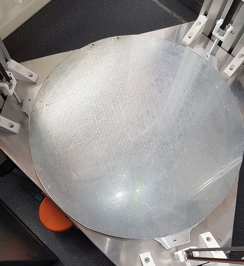
I went ahead put some elbow grease into both surfaces with some 60 grit. First of all, I am still slightly sad that my shiny surfaces are gone now
") . There is a noticeable improvement in friction, but not to the point I feel confident it won't slip on me again.
. There is a noticeable improvement in friction, but not to the point I feel confident it won't slip on me again.I think I am going to try putting three dowel pins in there next.
-
good night,
I have this configuration and it works very well.
From top to bottom:
0.2mm PEI
3M
Black barbecue paint (for mini IR) as DC42 says
0.6mm ferric stainless steelmagnet adhesive foil Here from Amazon
3mm aluminum sheet
220v siliconeThe result really is very good. I have never moved and withstand temperatures of at least 120ºc. I use the hot bed to cure parts made with SAKATA PLA INGEO 850 in a closed environment. It momentarily loses grip but regains it when it cools. When I'm not printing, I'm not worried about this momentary loss.
-
I think I am going to try putting three dowel pins in there next.
3 pins is too overconstrained. With 2 pins the system is already overconstrained, adding even more just increases the risk of bulging when things heat up/cool down due to different thermal expansion rates of the different metals.
Ideally you want one pin in a round hole and one in a slotted hole, where the slot must be in parallel to the line between the pins. Like this, in bad ASCII art:
(.) (=.=)the . is the dowel pin, the holes, well, you can guess that I suppose.
The first pin fixes the relative locations of aluminium and steel, but one pin is not enough to prevent rotation. This is where the second one in the slotted hole comes in; it prevents rotation but allows the different expansions of steel and aluminium when the assembly heats up, keeping the steel build surface flat.
If you have no means to create an accurate slot two round holes will do, if you place the dowel pins fairly close together. Do both in one corner, 20mm apart or so.
-
@DaBit said in Fixing a slippery magnetic bed?:
I think I am going to try putting three dowel pins in there next.
3 pins is too overconstrained. With 2 pins the system is already overconstrained, adding even more just increases the risk of bulging when things heat up/cool down due to different thermal expansion rates of the different metals.
Ideally you want one pin in a round hole and one in a slotted hole, where the slot must be in parallel to the line between the pins. Like this, in bad ASCII art:
(.) (=.=)the . is the dowel pin, the holes, well, you can guess that I suppose.
The first pin fixes the relative locations of aluminium and steel, but one pin is not enough to prevent rotation. This is where the second one in the slotted hole comes in; it prevents rotation but allows the different expansions of steel and aluminium when the assembly heats up, keeping the steel build surface flat.
If you have no means to create an accurate slot two round holes will do, if you place the dowel pins fairly close together. Do both in one corner, 20mm apart or so.
I indeed do not have access to means of cutting slots.
All valid points. I am still debating doing just one pin in the center of the bed. This eliminates the overconstraining, only allowing for straight up rotation. I feel the friction is not adequate for sheer forces but will be sufficient against rotation. The major downside to the center pin is ruining the most used part of the bed by sanding the pin to length you inevitable touch the PEI as well. Even if I were to take the pin out to make it to length, there would still be a hole in the center where there is steel in stead of PEI.
-
I would consider the center as an impractical location. An edge is much more convenient, and an 'oops' has much less impact. The dowel pins don't care; there is as much force near the edge as there is in the center.
I would ask a small local machineshop with a manual mill to do the holes. Nothing wrong with asking for help if you lack the tools or skills; one hand washes the other and those guys usually love to help someone who is creating something. It is very little work for them to create two 5.0mm deep blind holes in the aluminum and the accompanying holes in the steel. It would take me 15 minutes or so in my hobby shop, professionals should be even faster than that.
When a half decent machinist creates the holes you can also get away with blind hole/slot in the steel and use dowel pins with 6mm length (just buy standard ground and hardened pins). That way your PEI will not be interrupted at all.Just walk in, preferrably through the rear door or storage area entry to avoid operation human shield, ehrm, the frontoffice, and bring a box of cookies for the guys or offer to print a set of plastic soft jaws for their bench vises or so. One hand washes the other.....
-
@DaBit said in Fixing a slippery magnetic bed?:
I would consider the center as an impractical location. An edge is much more convenient, and an 'oops' has much less impact. The dowel pins don't care; there is as much force near the edge as there is in the center.
I would ask a small local machineshop with a manual mill to do the holes. Nothing wrong with asking for help if you lack the tools or skills; one hand washes the other and those guys usually love to help someone who is creating something. It is very little work for them to create two 5.0mm deep blind holes in the aluminum and the accompanying holes in the steel. It would take me 15 minutes or so in my hobby shop, professionals should be even faster than that.
When a half decent machinist creates the holes you can also get away with blind hole/slot in the steel and use dowel pins with 6mm length (just buy standard ground and hardened pins). That way your PEI will not be interrupted at all.Just walk in, preferrably through the rear door or storage area entry to avoid operation human shield, ehrm, the frontoffice, and bring a box of cookies for the guys or offer to print a set of plastic soft jaws for their bench vises or so. One hand washes the other.....
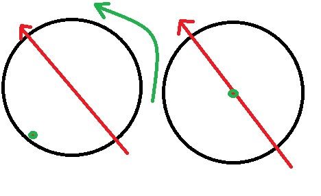
I agree, the center is impractical in terms of the machining. I also agree that the total force is always the same, no matter where the pin is located. However, the effective force is not the same. For example, the left design with the green pin on the edge will have much lower resistance against rotation/sliding rotation due to the force indicated in red. In the right example the effective moment of rotation is proportional to the distance from the center. And since the center is (with me) the most used area of the bed, the moment is the smallest.
That is why, from that POV, the center is the ideal place for a pin. At least that is how I see it.
All of this aside, I think I am going to drill holes at the side, but limit to two. I just cannot risk ruining the center of my bed. Added to that, I have TCO's mounted on the underside of the alu plate (in the center).
-
Yes, with the pin at the edge there is a location where the moment force is twice as large, and a significant part of the bed where the force is larger. However, if the system is that critical I would go back to the drawing board. Things usually get worse when they wear and age.
Moments being the lowest at the center of the bed is not important; you have chosen the bed size to be able to use it.
Two dowel pins at any distance resist moment, but further apart the forces are lower, the impact of play between pin/holes is lower, and the side effects of thermal expansion are more pronounced.
When i suck on my thumb I would say that 20-50mm apart is plenty.
-
I went ahead and drilled two holes near the edge of the bed and made some diy pins. The pins are 3mm diameter and spaced 60mm apart. Since hand drilling not really precise and a fabricated the pins from a nail, I epoxied the pins in the blind holes.
The result is decent, there's some play in the top plate's holes. Though you really have to grab the bed to be able to move it. If my printhead exerts the force needed to move it against the print, I believe I have biggert issues .
(agreed, the machine shop with off the shelf pins route would be nicer, but for a number of reasons I did not go that way).