@nxt-1
I think this flex/bed-sagging might be compensated is some part by the leverage of the system.
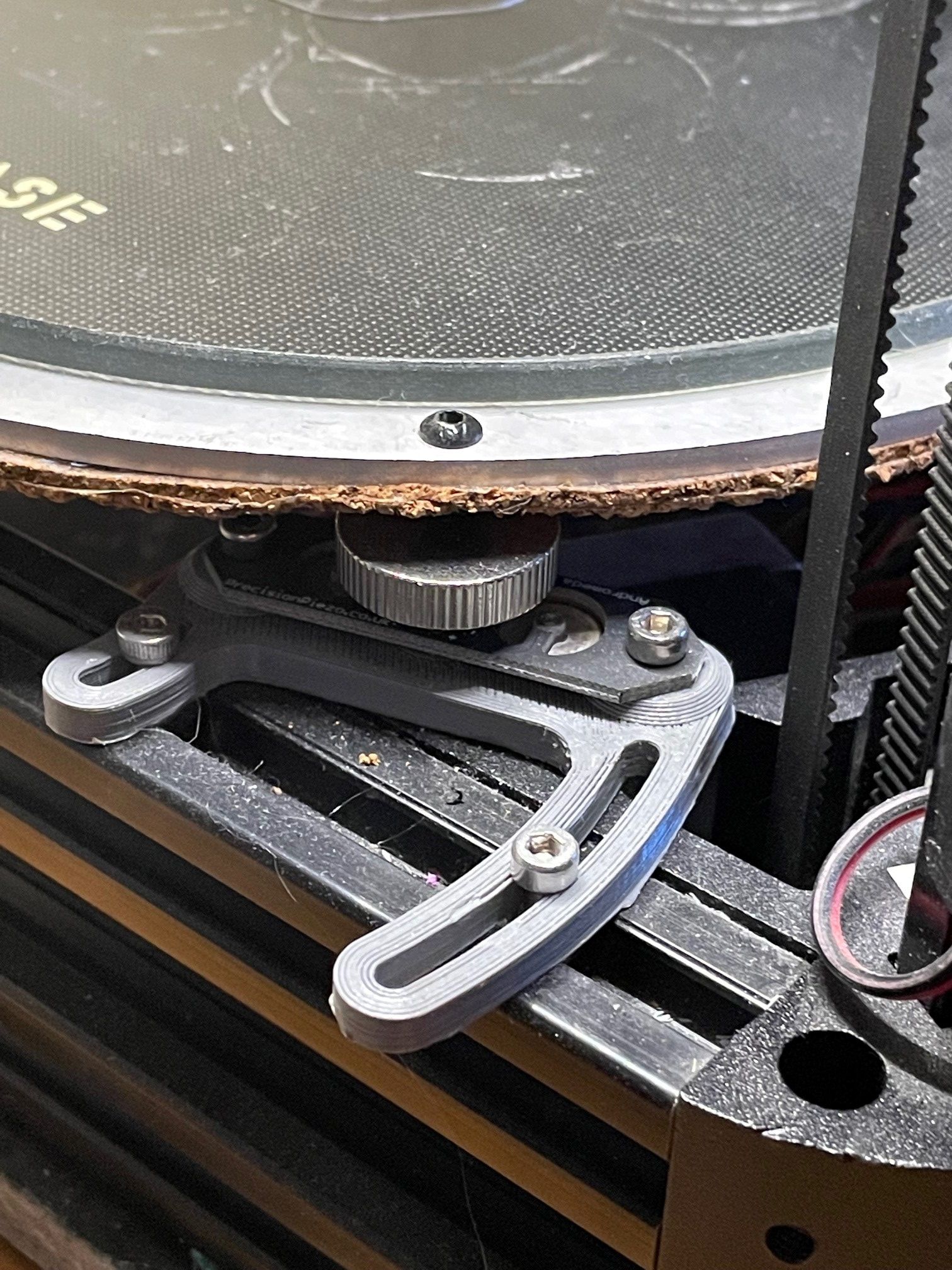
The piezo sensors furthest from the probe point are being flexed by the bed as well as the piezoelectric sensor closest to the probe point but the deflection at those point is larger because the probe point is acting as the input of a third class lever with the closest piezo sensor acting as the fulcrum and the further-away sensors are the load.
I suspect the maximum deflection at any point before a signal is detected would need to be a higher frequency harmonic of your sketch with a proportionally smaller deflection amplitude at each anti-node. Since I feel like this is getting into Laplace Transform territory I have to admit my math skills aren't up to quantifying this.
I expect there are a few "worst" places to probe (the midpoint between two sensors for example) which produce low-magnitude signals at two sensors and do not have any moment producing a signal at the remaining sensor.
Anywhere inside the triangle enclosed by the three sensors should produce a signal at all three sensors. Any point outside the line connecting two sensors would produce a signal at the third sensor with negative magnitude (because now its a first-class lever) and that might cause some odd behaviour depending on how the signals are processed in the probe's firmware but so far my installation hasn't had problems interpreting probe results at those locations.
If a very large round bed experiences this sort of measurement inaccuracy then I would suggest the bed is under-supported or under-built anyway and the bed dishing could/should be dealt with by some combination of stiffening and a better multi-point support system similar to that used for telescope mirrors.
