Unwarp Heatbed?
-
@devleon said in Unwarp Heatbed?:
I'll look around if I can source a 235x235x5mm plate.
here is one with pei on it
https://clever3d.de/epages/7a4290fc-7c7f-46cc-9b99-eadef22228e2.sf/de_DE/?ObjectPath=/Shops/7a4290fc-7c7f-46cc-9b99-eadef22228e2/Products/c3d-DDP-PEI-natur -
Cast aluminum tooling plate is sold under different brand names- EcoCast, MIC6, Alca5 are a few of the names to look for. It comes milled flat on both sides. There are many sellers on ebay who sell the stuff. You don't have to find an exact size match- you can cut the stuff with a hacksaw to whatever size you need from a larger plate. You can easily drill aluminum with any hand drill.
If you mount the plate on 3 leveling screws it will be easy to tram and will stay trammed. You might even be able to live without auto leveling and flatness compensation (I don't use either). If you really want optimal performance, use a kinematic mount that will allow the bed plate to expand when heated without pushing against the leveling screws and bending anything.
I have put 300mm square cast tooling plate beds in 3 printers including 2 bed slingers and it works fine. Here's the latest one.. Note that it is not necessary to use a milling machine to cut the slot in the plate. You can simply cut a slot from the edge with a saw. You can use acorn nuts on the ends of screws instead of the spherical head screws I used. I put the leveling screws on ears located as close to the bearing blocks as possible for maximum stability. You can put them elsewhere and it will still work fine.
-
Here is a pic of how my bed is set up
-
@devleon said in Unwarp Heatbed?:
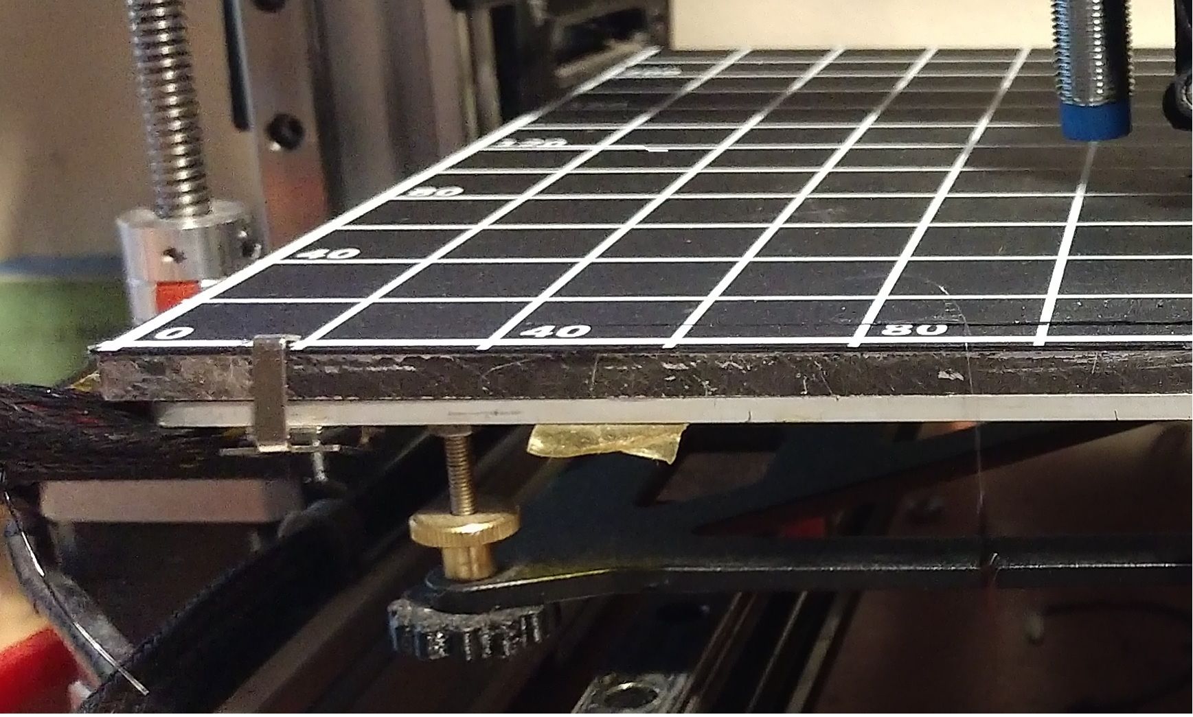
@stewwy The idea with the cast and milled aluminium heatbed doesn't sound too bad. I'll look around if I can source a 235x235x5mm plate. What kind of aluminium did you get? What I found with a quick google is EN AW-5083 / AlMg4,5Mn0,7, and I also read in a sheet somewhere that it can deform at around 70 degrees?
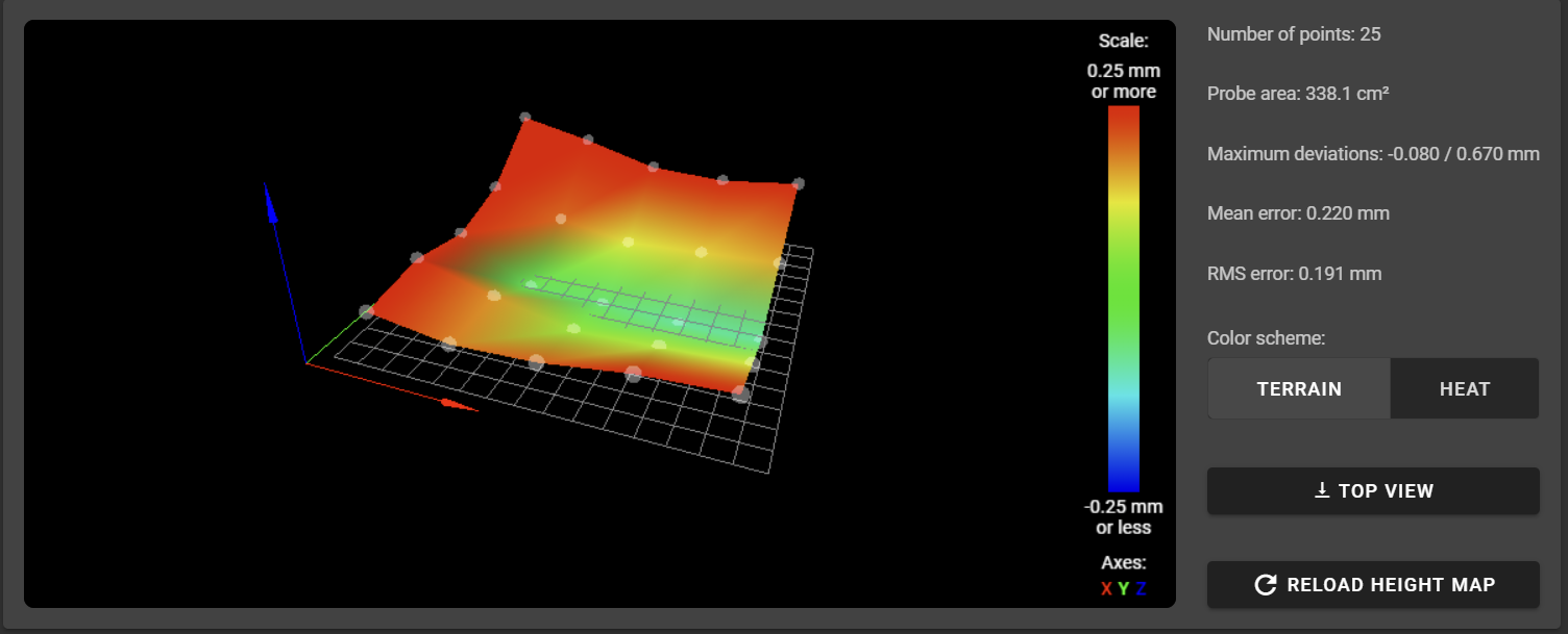
Also, currently my headbed looks like this, a mean error of 0.22mm (more than a layer), and a maximum deviation of 0.67mm (pretty bad...):
Maybe I should just put some masking tape in the middle, along the x-axis?
I'm surprised that mesh compensation isn't able to solve for that. I think you would get much better results with a more detailed mesh. You've only got a 5x5 grid of points. There are large gaps between them where it has to interpolate the position. Increasing the mesh density will likely give much better first layers and you won't need to drastically alter your bed.
-
@devleon said in Unwarp Heatbed?:
Maybe I should just put some masking tape in the middle, along the x-axis?
maybe you could put something underneath the middle of the bed that pushes it up just a little bit
-
@Phaedrux How many points should I do?
I was just doing 5x5 for now, so I can make adjustments to the bed and not have to wait minutes for probing to be done.I'll try some masking tape now and see if I can get a usable result.
-
if you use masking tape you will leaves a gap that will be bad for heat transfer.
do a probe with 10mm apart and post the picture. then see if there are irregularities. if not you can increase the probing distance.
i.e as long as the picture looks the same you can increase the probing distance. -
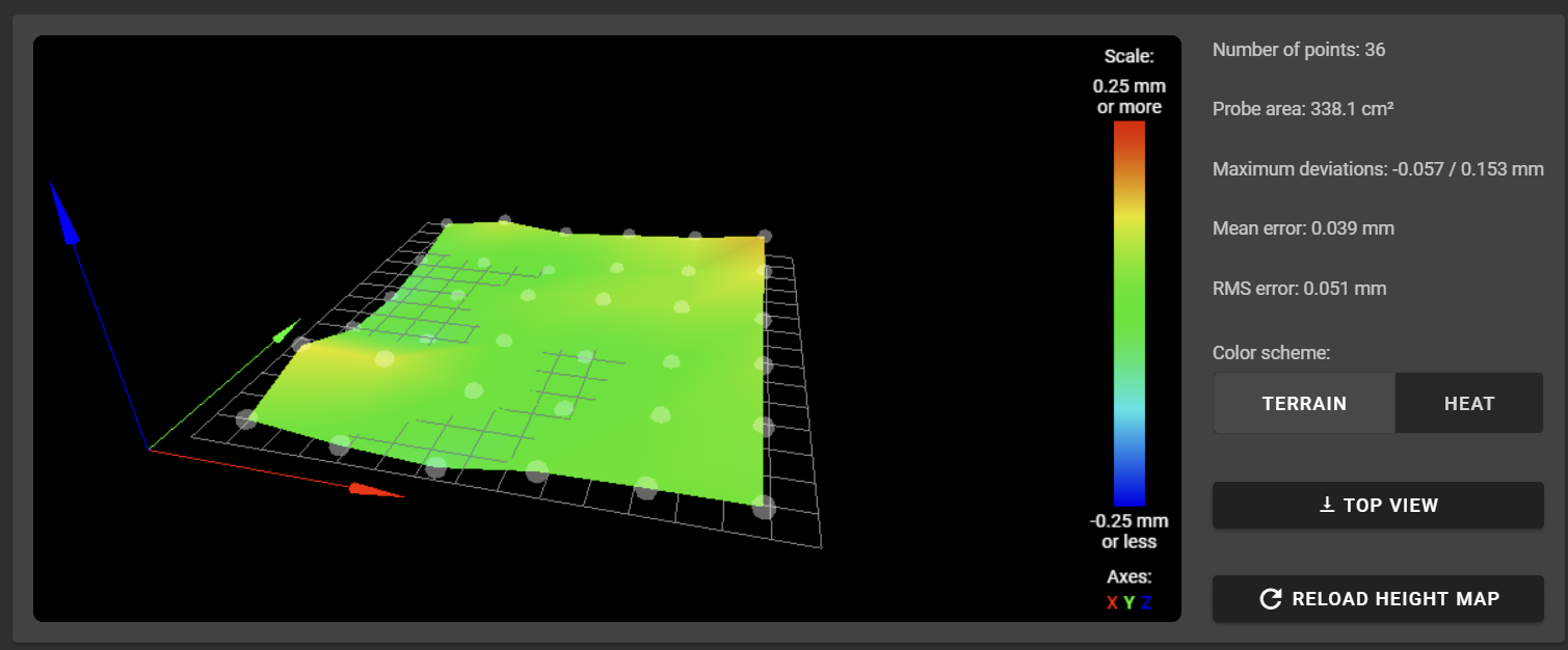
After applying some masking tape, this is the result I have so far. Definitely much better. I'll try printing some single layer discs at the corners now.
-
I just tried printing a perimeter around the maximal printable area, and get printing in the air (nozzle too high) at the right side, and the nozzle dragging across the print surface on the left side.
G29 S1 is part of my gcode file, and I can feel the z-stepper moving ever so slightly.How come my nozzle is still dragging into the printbed on one side, and printing in thin air on the other side?
-
It's possible that your config doesn't provide sufficient range for z compensation.
Try this: print a small object on the side where it's printed in thin air and see if you can make the first layer right using baby steps or by setting a small negative Z offset in your slicer. If can't make it to reach the surface, it means that the limits prevent the head getting close enough.
If this is the case, there are a few ways to address it. One is to do the bltouch Z homing near the low point (where printing in the air). Another is to increase the Z value of your G31 config command.
-
@devleon said in Unwarp Heatbed?:
@stewwy The idea with the cast and milled aluminium heatbed doesn't sound too bad. I'll look around if I can source a 235x235x5mm plate.
In the US you can get custom size here https://www.midweststeelsupply.com/store/castaluminumplateatp5
It's the kind of aluminum plate that is also known as Mic-6. They can be heavy though , not a good fit for a Y moving bed.
-
@devleon said in Unwarp Heatbed?:
After applying some masking tape, this is the result I have so far. Definitely much better. I'll try printing some single layer discs at the corners now.
It would appear that your bed has a bit of a tilt still. Low on the left side and high on the right side. Or perhaps you have some tilt on your X axis gantry or probe mount?
The higher density mesh shows that there is some peak and valley variation that's starting to appear. Try increasing the mesh density even further. Even though it takes longer, you can save it and reload it before the print without having to completely redo it every time.
You should do at least one mesh at the highest density possible to see what the surface of the bed really looks like.
What settings are you using for the BLTouch? You may be able to improve it's accuracy and repeatability with a few tweaks.
-
The bed definitely is still tilted a bit, but for now, I don't want to try to get it untilted and ruin the good state I have now.
A couple of things that I found out yesterday: even though I checked the X and Y offset of the probe during the CAD design of my custom mount, it seemed to be off by 10mm in the Y-axis, so I adjusted that. I also found out that the purge bucket I had attached to the right side of the X axis was hitting the top of my duet case, and the nozzle couldn't physically reach the bed. Not sure how I have missed that for so long, yet here we are.
So with that out of the way, I'm getting a nice first layer now. I'll definitely do a higher detailed map though. I guess 8x8 or something along those lines.
@Phaedrux said in Unwarp Heatbed?:
What settings are you using for the BLTouch? You may be able to improve it's accuracy and repeatability with a few tweaks.
That's what I have currently in my config.g regarding the BLTouch:
; Z-Probe M574 Z1 S2 ; Set endstops controlled by probe M307 H5 A-1 C-1 D-1 ; Disable heater on PWM channel 5 for BLTouch M558 P9 H5 F120 T6000 ; Set Z probe type to bltouch and the dive height + speeds G31 P500 X-62.5 Y-9 Z3.85 ; Set Z probe trigger value, offset and trigger height M557 X15:190 Y25:225 P6:6 ; Define mesh grid -
@devleon said in Unwarp Heatbed?:
M558 P9 H5 F120 T6000
G31 P500 X-62.5 Y-9 Z3.85Try G31 P25, and add to M558 A5 R0.5
-
@Phaedrux said in Unwarp Heatbed?:
@devleon said in Unwarp Heatbed?:
M558 P9 H5 F120 T6000
G31 P500 X-62.5 Y-9 Z3.85Try G31 P25, and add to M558 A5 R0.5
Thanks, I will try them out in the next days when I have time again to tinker with my printer.
I have another question - is it possible to decouple the Z-Probe + Mesh-Compensation and the Z-Limit Switch / Homing?
My idea is to use the magnetic and hot-swappable mounting solution I have now to mount a dedicated LJ12A3-4-Z inductive probe right where the hotend and nozzle would normally be. Because I'm swapping out the hotend with the probe, I won't be able to use it to home with the hotend attached, only to probe and measure the bed, and will have to remove it to be able to print.
Thus, I was thinking of using an additional physical z-endstop with a microswitch, while the nozzle is on the very far right side beyond the bed, and where it can actually go lower than the bed and can hit the physical z-stop. Then I just measure the offset and apply the mesh compensation I will do once in a while.
Does that make sense? How would I configure a seperate Z-Probe and Z-Limit Switch?
-
Yes that makes sense. You can do it, though your offset will need to be spot on since you won't be using the probe to home Z. Otherwise your heightmap could have a larger than expected offset. The trigger height of the switch would need to be offset to exactly where the nozzle would be touching the center of the bed.
You could find this offset with gcode as well. Touch the nozzle to the bed, use G92 to set Z0, You'll need to use M564 S0 to allow movement beyond the set axis limits and then jog the nozzle until it just triggers the switch and note the Z position. It'll be a negative value. This value would also change any time the bed was releveled. This is a disadvantage to not using the probe to home.
Your homeall.g could be modified to move the print head to where it needs to be, configures the endstop, and then triggers it setting the Z position with a G92. Then you'd have to return back above the bed surface and move to a safe location to start the print from.
For the probing of the mesh you could edit bed.g to configure the probe, prompt you to ensure it's mounted, and then execute a G29 to generate the heightmap, and then prompt you to reinstall the nozzle.
Hopefully that makes sense. Let me know if you want more detailed macro examples.