Duet 3 3 z motors config
-
Help needed.
I am trying to set up a core xy with 3 z motors. And I think I have sent myself insane trying to set it up. Not much point posting my config files as I have edited it so many times, I go cross eyed trying to figure out what I have done. But nothing has worked so far.
So if any of you kind people could share your config etc files, so I could compare to what I have, I would really appreciate it.
TIA
Matthew
-
@mattbaker Are you using a Duet 3 6HC with 3HC expansion board? What seems to be the problem?
Ian
Bed-slinger - Mini5+ WiFi/1LC | RRP Fisher v1 - D2 WiFi | Polargraph - D2 WiFi | TronXY X5S - 6HC/Roto | CNC router - 6HC | Tractus3D T1250 - D2 Eth
-
@mattbaker said in Duet 3 3 z motors config:
I am trying to set up a core xy with 3 z motors.
normally you do not need to do more than add the extra motors to the M584 line like
M584 X0 Y1 Z2:4:5 E3current acceleration etc. is the same for all z motors
see this article for more information and extra stuff
https://duet3d.dozuki.com/Wiki/Bed_levelling_using_multiple_independent_Z_motors -
@mattbaker One of the gotchas on Duet 3 wiring is that the motor driver layout:
2 3
1 4
0 5not
2 5
1 4
0 3See:
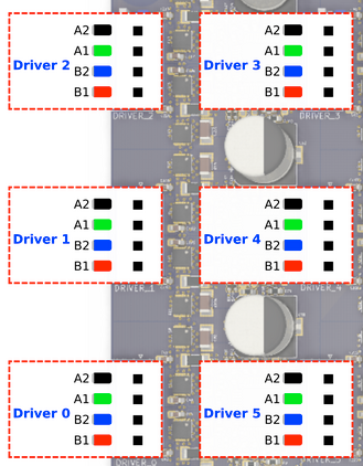
Make sure the motors are plugged into the right headers!Ian
-
Ive wired the steppers correctly, found that one out the hard way.
I'm trying to get the 3 axis levelling working.
-
@droftarts I'm trying to get the 3. axis levelling working. I'm using the Duet 3 6HC. without the expansion board at present.
-
@mattbaker Okay. See the link @Veti posted earlier. You need the following for bed levelling with 3 independent Z motors:
- to know which motor driver links to which leadscrew, eg Z2 is front left, Z3 is back centre, Z4 is front right
- Leadscrew position defined by M671, in the order the leadscrews are defined by M584!
- Change bed.g to probe as near as possible to each leadscrew
For details, see https://duet3d.dozuki.com/Wiki/Bed_levelling_using_multiple_independent_Z_motors#Section_Example_for_3_motors
Ian
-
Ive gone back through it and changed the config however I keep getting g30: some computed corrections exceed limit of 5.00.
Ive tried changing the limit, you see in some videos distances of 20+ mm, and it just seems to get ignored.
M671 X480:230.0:-30 s100 Y460.0:-40:460 S100
-
@mattbaker your m671 doesn’t look right.
Here’s mine. For reference the order of the z axis motors are one on the left is motor one, motor on the back right is two, motor on the front right is the third. All commands are listed/referenced with that order. I also always include a pin map in the beginning of my config.g as an easy reference.
; Configuration file for Duet3 (firmware version 3.0 RC2)
; executed by the firmware on start-up
;
; --------------- Pin/connection Mapping Legend -------------------
; out0 - Bed heater
; out1 - Extruder 1 heater
; out2
; out3
; out4 - Radiator cooling fan - WC heatsink
; out5
; out6
; out7
; out8 - Parts cooler on printhead
; out9 - Duet board cooling fan
; out4.tach - Radiator cooling fan rpm wire - WC heatsink
; out5.tach
; out6.tach
; io0.in
; io1.in - X min active low endstop switch
; io2.in - Y max active low endstop switch
; io3.in - Z probe type to bltouch - DEPRECATED
; io4.in - Z probe type to PIEZO
; io5.in - Emergency stop switch
; io6.in
; io7.in
; io8.in
; io0.out
; io1.out
; io2.out
; io3.out - GPIO port 0 on IO3, servo mode - BLTouch Z-Probe
; io4.out
; io5.out
; io6.out
; io7.out
; io8.out
; servo, out10 (only on v0.5, not on v0.6)
; pson
; spi.cs0
; spi.cs1
; spi.cs2
; spi.cs3
; temp0 - Bed Thermistor
; temp1 - PT1000 for extruder 1
; temp2 - PT1000 for pi4
; temp3
; mcu-temp - MCU sensor
;
; -----------------------------------------------------------------
;
; General preferencesG4 P2000 ; Hold your Horses.
G90 ; send absolute coordinates...
M83 ; ...but relative extruder moves
G21 ; Set units to Millimeters
M550 P"DUET3" ; set printer nameM584 X0.3 Y0.2 Z0.0:0.1:0.4 E0.5 ; set drive mapping to each axis
M669 K1 ; Select CoreXY mode - New format; Network
M552 S1 ; enable network
M552 P192.168.3.120 ; Static IP Address
M586 P0 S1 ; enable HTTP
M586 P1 S0 ; disable FTP
M586 P2 S0 ; disable Telnet; Drives
M569 P0.0 S0 ; physical drive 0 goes backwards - Z Axis Left (1)
M569 P0.1 S0 ; physical drive 1 goes backwards - Z Axis Right Back (2)
M569 P0.2 S0 ; physical drive 2 goes backwards - Y Axis
M569 P0.3 S0 ; physical drive 3 goes backwards - X Axis
M569 P0.4 S0 ; physical drive 4 goes backwards - Z Axis Right Front (3)
M569 P0.5 S1 ; pyhsical drive 5 goes forwards - Extruder 1; Set up three Z-axis location
M671 X-52.5:377.5:377.5 Y162.5:282.5:42.5 S5 ; leadscrews at 1 - left, 2 - rear right and 3 - front rightM92 X200.00 Y200.00 Z400.00 E1800 ; set steps per mm
M350 X16 Y16 Z16 E16 I1 ; configure micro-stepping with interpolation
M566 X1000.00 Y1000.00 Z400.00 E240.00 ; set maximum instantaneous speed changes (mm/min)
M203 X24000.00 Y24000.00 Z2000.00 E1200.00 ; set maximum speeds (mm/min)
M201 X10000.00 Y10000.00 Z400.00 E800.00 ; set accelerations (mm/s^2)
M906 X1000 Y1000 Z1000 E800 I30 ; set motor currents (mA) and motor idle factor in percent*100
M572 D0 S0.074 ; Set pressure advance
M84 S30 ; Set idle timeout; Axis Limits
M208 X0 Y0 Z0 S1 ; set axis minima
M208 X320 Y320 Z350 S0 ; set axis maxima; Endstops
M574 X1 S1 P"io1.in" ; X min active high endstop switch
M574 Y2 S1 P"io2.in" ; Y max active high endstop switch; Z-Probe - BLTouch - DEPRECATED
; M574 Z1 S2 ; set endstops controlled by probe
; M558 P9 C"^io3.in" H3 F60000 T10000 ; set Z probe type to bltouch and the dive height + speeds (bltouch NEEDS pullup)
; G31 P10 X28.5 Y-5 Z2.35 ; set Z probe trigger value, offset and trigger height; Z-Probe - PIEZO
M574 Z1 S2 ; set endstops controlled by probe
M558 P8 C"io4.in" H5 F1000 T20000 ; set Z probe type to PIEZO and the dive height + speeds
G31 P10 X0 Y0 Z-0.1 ; set Z probe trigger value, offset and trigger heightG30 ; Probe Z
; Configure Heaters and Sensors
M308 S0 P"temp0" Y"thermistor" A"Bed Temp" T100000 B3950 ; Configure bed temperature sensor
M143 H0 S120 ; set temperature limit for heater 0 to 120C
M308 S1 P"temp1" Y"pt1000" A"Extruder 1 Temp" ; Configure extruder 1 temperature sensor - PT1000 sensor
M143 H1 S280 ; set temperature limit for heater 1 to 280C
M308 S2 P"mcu-temp" Y"mcu-temp" A"Duet Board" ; Configure MCU sensor
; M308 S4 P"temp2" Y"pt1000" A"RPI" R2200 ;Pt1000 temp sensor for the raspberry pi; Define Sensors and Fans
M950 H0 C"out0" T0 ; Define heater 0 (bed heater) - bed_heat pin and Temp Sensor 0
M950 H1 C"out1" T1 ; Define heater 1 (hot-end E0) to use the "e0_heat" pin and Temp Sensor 1;Set PID values
M307 H0 A253.9 C566.2 D1.0 V23.3 B0 ; disable bang-bang mode for the bed heater and set PWM limit
M307 H1 A855.8 C368.4 D5.7 V23.3 B0 ; disable bang-bang mode for the extruder heater and set PWM limitM950 F0 C"out8" Q100 ; Define Fan_0 for use - Parts Cooler on Printhead - 4010 fan
M950 F1 C"!out4+^out4.tach" Q25000 ; Define Fan_1 for use - Radiator cooling - WC heatsink. - PWM fan
M950 F2 C"out9" Q25000 ; Define Fan_2 for use - Duet board cooling fan
; M950 S0 C"io3.out" ; Define GPIO port 0 on IO3, servo mode - BLTouch Z-Probe - DEPRECATED; Fans
M106 P0 S0 ; set fan 0. Parts Cooler on Printhead
M106 P1 T25:40 H2 ; Set fan 1. Manages Radiator fan for water-cooled loop.
M106 P2 T35:50 H2 ; Set fan 2. Manages Duet board fan.; Tools
M563 P0 S"Extruder 1" D0 H1 F0 ; define tool 0. Fan 0 operates with an active hot-end
G10 P0 X0 Y0 Z0 ; set tool 0 axis offsets
G10 P0 R0 S0 ; set initial tool 0 active and standby temperatures to 0C; Emergency Stop
M574 S1 P"^!io5.in" ; Define Emergency endstop - emergency stop switch condition
M581 P"io5.in" T0 ; Define action to be taken with activation of emergency stop switch; Miscellaneous
T0 ; select first tool
M501 ; Store parameters -
@Nuramori Thanks for your help. I uploaded new files from the configurator, changed a few things, which I thought is what I had, and problem solved.
No idea what the problem was, looks the same to me, but I'm not going to look a gift horse in the mouth.