CR-10S5 Firmware
-
Also, what is a U3?
-
-
@Gost101 said in CR-10S5 Firmware:
Alrighty, so I was able to print fast, but my power supply died on me mid print. Lol, I confirmed it was not the board. I will be buying 2 of these power supplies and wiring them together just as I have done on my other 3D printers, plus it will be more quiet. I will then print the volcano adapters and a case for the duet wifi to sit in.
IMHO I would not use those 2 tiny PSU's, I would buy something like this Mean Well NES-350-12 12V 350 Watt, https://www.amazon.com/NES-350-12-Switching-Power-Supply-110-240/dp/B007K2H0GI/ref=sr_1_1?ie=UTF8&qid=1526920350&sr=8-1&keywords=Mean+Well+NES-350-12
P.
-
@PaulHew Well that's a bit to late I already purchased them and spliced them. They are already good to go. Is this covered under the warranty for replacement. As the fuse did not trip, the circuit breaker connection to the wall did not trip, and was not caused by faulty wiring( the new power supply was not wired up at the time of discovery( I found this after unplugging all the wires to install the new power supply as I assumed the power supply died. I have a video that I can post of the configuration before I removed all the wires if you need that.
-
@Gost101 said in CR-10S5 Firmware:
that's a bit to late
its never too late to listen to good advice.
I already purchased them and spliced them
please un-splice the positive power, disconnect BED+ and splice those two wires, do not connect to duet. leave the negative power spliced to common ground and leave the other hot bed wire on BED-.
this way you'll spread the load instead of trying to make two supplies not made to work in parallell do so. (presuming the bed is the 220w type, might not have been the most reliable source i found)
-
This post is deleted! -
I asked you to measure if the ground terminal of the Vin connector shows connectivity to the other ground pins around the board. If you don't have a meter or are able to follow simple instructions there isn't a whole lot of troubleshooting we can help you with.
-
@bearer I don't have a multimeeter and after this problem with the board I was hoping to be able to get a replacement.
-
Then sit back and wait for the admins to evaluate.
-
Cool beans. I removed the image.
-
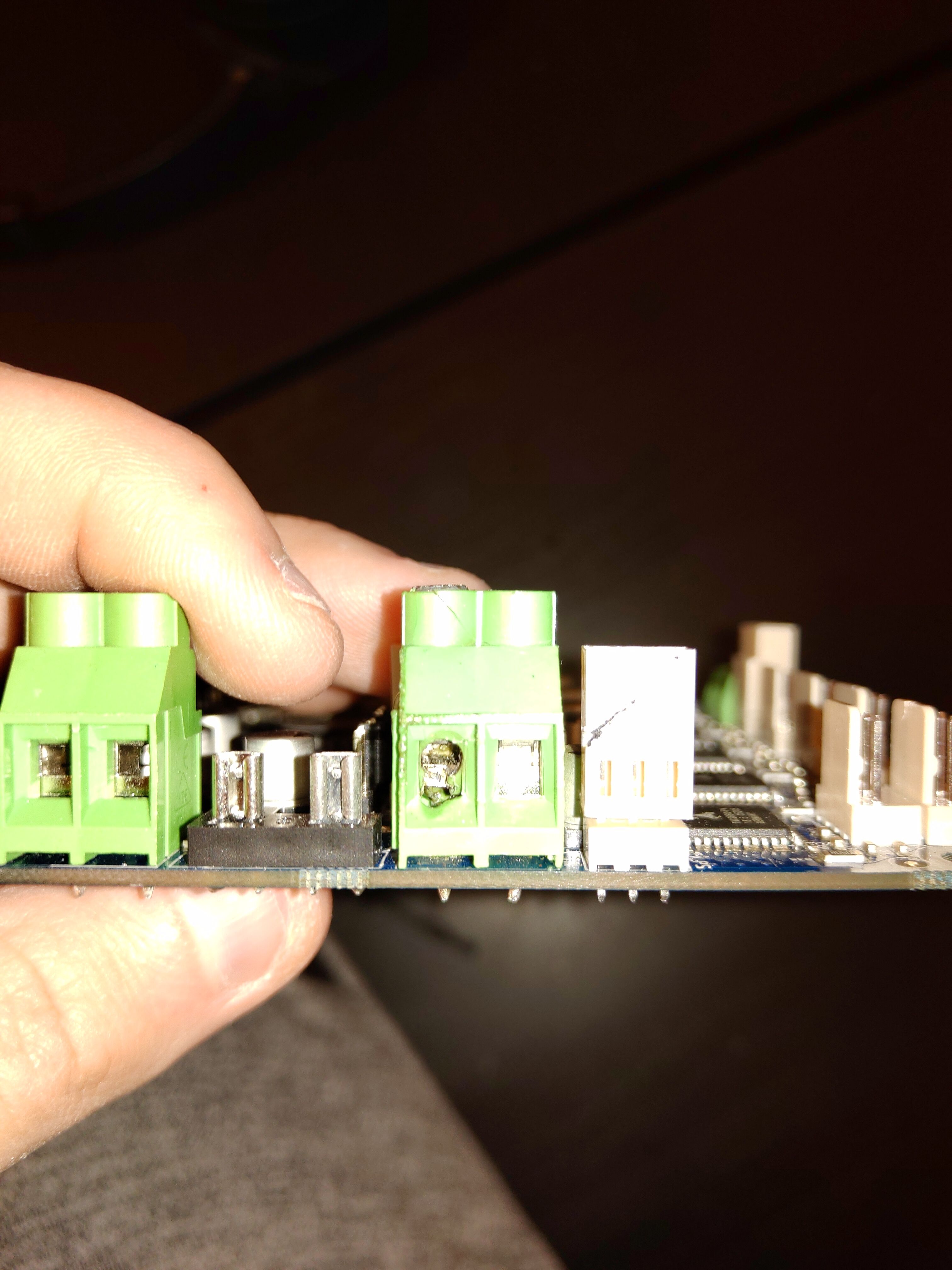
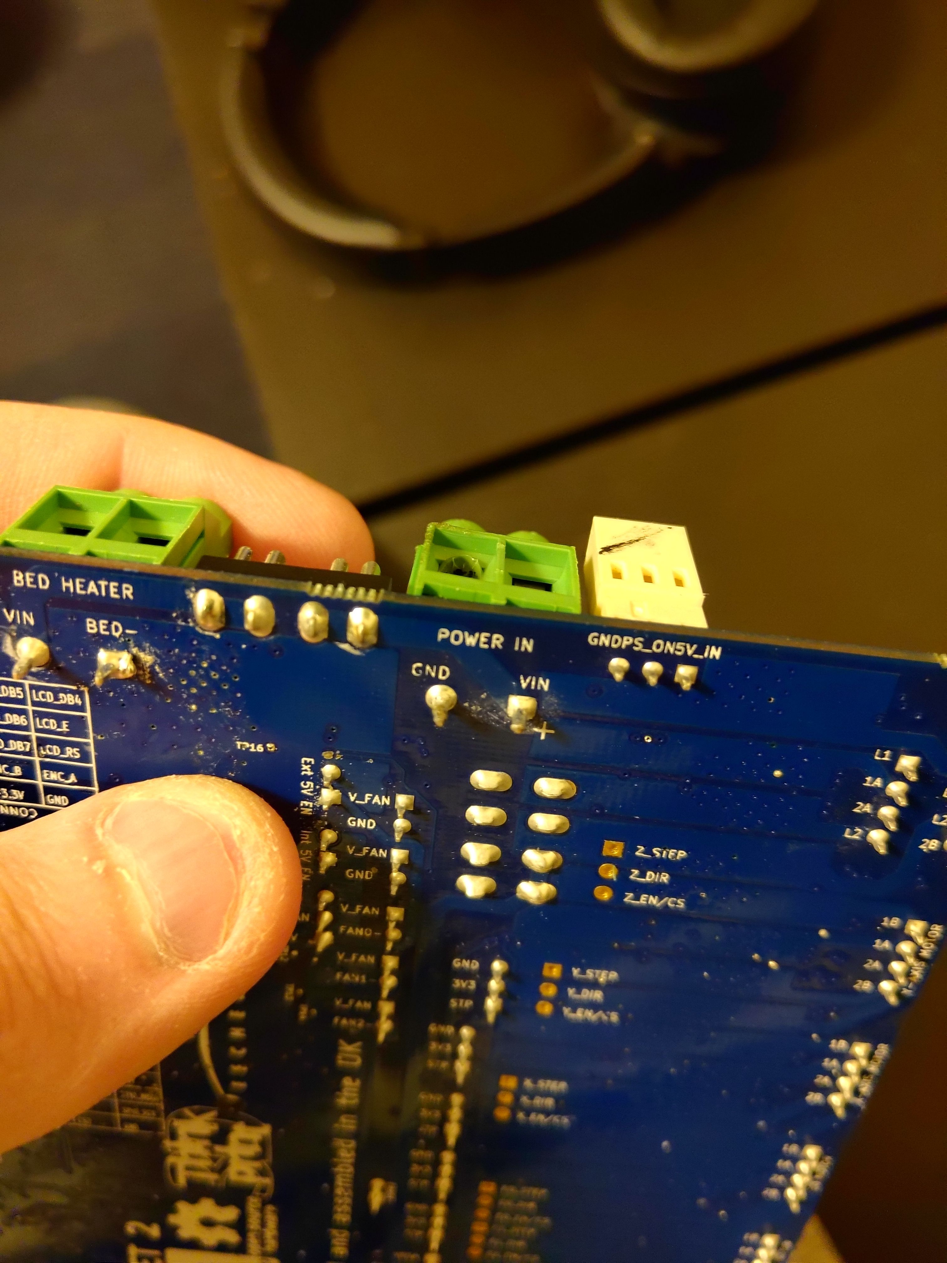
@Gost101 Please take a picture of the soldering on the back of the board around the area of the terminal, it's not clear on your earlier end-on picture. The only reason the board would be replaced under warranty is if the soldering was faulty, but the terminal would tend to melt around the pins. An melted terminal, particularly where this one has melted (at the screw terminals) usually indicates a poor wiring connection, which then heats up. Take a picture of the wires that were connected to the terminal. Were they well-crimped in a ferule? Were they of sufficient size (AWG) to carry the load? Were they fully-tightened in the screw gate? See https://duet3d.dozuki.com/Wiki/Power_Wiring. If the current draw is below the rated value of the fuses, they won't blow; they can only provide protection from short circuit causing a high current draw. What current is your heated bed and hot end?
I don't see any damage to U3, so would expect that, once you can get power in on the main terminals, the board will be fine. I expect that the easiest thing to do will be to replace the screw terminal block yourself, which has probably failed internally, though it may have burned the copper trace on the board below it. Components for the Duet are listed here: https://duet3d.dozuki.com/Wiki/Connector_and_spare_part_numbers#Section_Screw_Terminals
Ian
-
@droftarts Yes they were connected in the included wire connectors. I no longer have the wires that were connected to the board as I thought the original power supply was dead. But I will look through the trash to find them. Yes they were fully tightened appropriately.
-
@droftarts


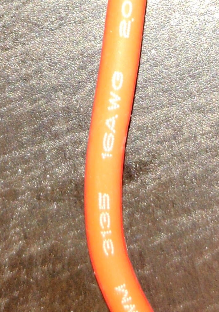 I couldn't find the wire, but here is a picture of the same gauge wire used on the original power supply connecting to the power on and off switch.
 -
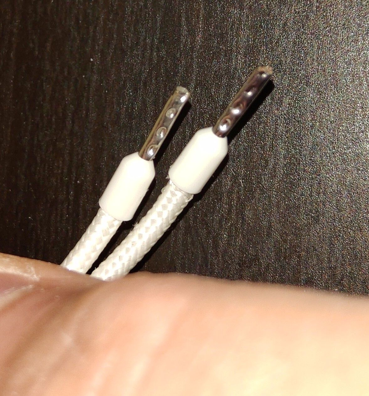
@droftarts The connectors that were crimped to the wire we're ones similar to these:
-
@droftarts The hotend can go up to 65w at 550, but I have only been printing in pla at 190. The heated bed is up to 110w, I normally keep it around 50
-
@Gost101 The soldering looks fine. Earlier pictures show it loose on the desk; moving it around can certainly loosen the wiring. We do recommend that you check the wiring, and tighten the screw terminals, after a few hours of operation.
You said that the PSU failed; did it? It would be odd if the PSU did fail at the same time; a wiring fault like this does not usually kill the PSU as it's not drawing more current, but a short circuit that is not protected by a fuse (ie direct short of VIN to GND) would cause the PSU fuse to blow (probably the internal one). How was the Duet mounted? You posted a recent picture looking like it's taped to the PSU. The pins on VIN and GND underneath the board are quite long, could they have been in contact with, or close enough to arc to, the metal case of the PSU? Or could something else have shorted VIN and GND pins underneath? This would have melted the wiring at the weakest point, ie at the screw terminal.
Unfortunately, we don't feel this is a candidate for warranty replacement. However if you email info@duet3d.com linking this forum thread, we may be able to offer a refurb/repair at cost.
Ian
-
Yes they were fully tightened appropriately.
pray tell how does one fully and appropriately tighten one of those? ..not that it actually matters; there are imo too many other fishy statements, otherwise I'd offer to replace the Vin terminal for parts and postage.
-
Not sure if it's worth mentioning the scorch mark on the 3 pin 5V In connector next to the Power In connector. I didn't see it in the post.
-
Oh, its been spotted and put on the fishy list (suppose it could be tape residue). The two pictures of the bottom of the board doesn't look to be quite the same either, its the same board, but one looks cleaner and has scratches in the solder mask (suppose it could be down to lighting and angles, but meh, fishy stuff)
-
The thread is a bit long and all over the place plus the issue currently being discussed doesn’t match the title, all of which makes it a bit difficult.
I didn’t see the machine spec (bed and hotend wattage) and cable length.
16ga wire @ 12 volts is too small for Vin. The brick style power supplies are also not a good choice and the wires are probably undersized (like 18ga).
If it isn’t an obvious short to the underside as mentioned earlier, I would suspect that this has been an issue for some time but wasn’t noticed until it became a problem. The excessive heat through expansion and contraction could have loosend the connection and the voltage drop across the Vin wires was too much causing the meltdown.