Duet3D Logo Duet3D
    • Tags
    • Documentation
    • Order
    • Register
    • Login

    Duet 3 5V issue

    Scheduled Pinned Locked Moved
    Duet Hardware and wiring
    4
    16
    504
    Loading More Posts
    • Oldest to Newest
    • Newest to Oldest
    • Most Votes
    Reply
    • Reply as topic
    Log in to reply
    This topic has been deleted. Only users with topic management privileges can see it.
    • OscarGMundefined
      OscarGM
      last edited by

      When I try to connect my Duet 3 to my BLV Mgn Cube It doesn't supply the 5V neither SBC nor BLT, after that I plugged the usb cable to Duet 3 and both work fine, but the internal 5V doesn´t work, I Try to change the 5V jumpers configuration without success.
      I think that my internal 5V supply is dead. Any idea to make it work?

      1 Reply Last reply Reply Quote 0
      • A Former User?
        A Former User
        last edited by

        Just for clarity the default settings did not give you 5V LED when you apply Vin? (if so then, yes, sounds like its faulty)

        From the wiki:

        The default 5V power configuration is Internal 5V enable - jumpered, 5V->SBC jumpered (the Duet is powering the SBC) , SBC->5V* not jumpered. If you want the SBC to provide 5V to the Duet then remove the jumper from 5V->SBC and from Internal 5v En. Place a jumper on SBC-5V*. NOTE this bypasses the 5V protection and a fault on the SBC may damage the Duet.

        OscarGMundefined 1 Reply Last reply Reply Quote 0
        • dc42undefined
          dc42 administrators
          last edited by

          Is the 5V_IN jumper definitely in place?

          Is the 12V supply working? If so then the amber LED should be lit. If not, check the VIN fuse.

          Duet WiFi hardware designer and firmware engineer
          Please do not ask me for Duet support via PM or email, use the forum
          http://www.escher3d.com, https://miscsolutions.wordpress.com

          OscarGMundefined 1 Reply Last reply Reply Quote 0
          • OscarGMundefined
            OscarGM @A Former User
            last edited by

            @bearer yes the 5V Led is off

            1 Reply Last reply Reply Quote 0
            • OscarGMundefined
              OscarGM @dc42
              last edited by

              @dc42 yes the jumper is in place and 24V PSU is supplying the board but the 5V led is off.

              1 Reply Last reply Reply Quote 0
              • A Former User?
                A Former User
                last edited by

                And the other LEDs (with Vin connected)?
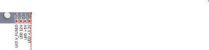
 d6de8419-9023-4ab6-8a4b-9e2979a0c329-image.png

                OscarGMundefined 1 Reply Last reply Reply Quote 0
                • OscarGMundefined
                  OscarGM @A Former User
                  last edited by OscarGM

                  @bearer 24V only
                  V_Fused and 12V Leds on
                  24V+USB
                  4 Leds on

                  droftartsundefined 2 Replies Last reply Reply Quote 0
                  • A Former User?
                    A Former User
                    last edited by

                    Its over to @dc42 at this time i think

                    1 Reply Last reply Reply Quote 0
                    • droftartsundefined
                      droftarts administrators @OscarGM
                      last edited by

                      @OscarGM From those pictures, with 24V input there's no 5V or 3.3V LEDs, they only light up with USB power. It also looks like jumpers are on 'Internal 5V enable' and '5V->SBC' correctly. I can only assume the 5V regulator is dead, but can't see any damage to it. @dc42 to confirm?

                      Ian

                      Bed-slinger - Mini5+ WiFi/1LC | RRP Fisher v1 - D2 WiFi | Polargraph - D2 WiFi | TronXY X5S - 6HC/Roto | CNC router - 6HC | Tractus3D T1250 - D2 Eth

                      1 Reply Last reply Reply Quote 0
                      • droftartsundefined
                        droftarts administrators @OscarGM
                        last edited by

                        @OscarGM The 5V regulator is the 8-pin chip by the corner of the inductor marked 6R8. Yours (bottom right):

                        99c8e137-3c20-4a7a-b186-964866df1985-image.png
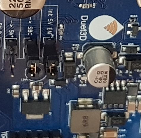
                        I can't see anything obviously wrong. @dc42 ?

                        Ian

                        Bed-slinger - Mini5+ WiFi/1LC | RRP Fisher v1 - D2 WiFi | Polargraph - D2 WiFi | TronXY X5S - 6HC/Roto | CNC router - 6HC | Tractus3D T1250 - D2 Eth

                        OscarGMundefined 1 Reply Last reply Reply Quote 0
                        • A Former User?
                          A Former User
                          last edited by A Former User

                          Looking closer the part to the left of it isn't level, but are you sure about that being the 5V regulator? (Schematic says U5 and tiny 16 pin QFN chip) (Wrong board)

                          droftartsundefined 1 Reply Last reply Reply Quote 0
                          • OscarGMundefined
                            OscarGM @droftarts
                            last edited by

                            @droftarts I don't know if this can clarify something https://www.dropbox.com/s/cxmiagz20t1ytjx/5V%20Regulator%20Duet%203.jpg?dl=0)

                            1 Reply Last reply Reply Quote 0
                            • dc42undefined
                              dc42 administrators
                              last edited by

                              @OscarGM, thanks for your patience. I approve a warranty replacement for your Duet 3 main board,

                              Duet WiFi hardware designer and firmware engineer
                              Please do not ask me for Duet support via PM or email, use the forum
                              http://www.escher3d.com, https://miscsolutions.wordpress.com

                              OscarGMundefined 1 Reply Last reply Reply Quote 0
                              • OscarGMundefined
                                OscarGM @dc42
                                last edited by OscarGM

                                @dc42 thank you.
                                Do I have to do something about the process?

                                droftartsundefined 1 Reply Last reply Reply Quote 0
                                • droftartsundefined
                                  droftarts administrators @OscarGM
                                  last edited by

                                  @OscarGM I think you've already emailed us, I'll sort it out.

                                  Ian

                                  Bed-slinger - Mini5+ WiFi/1LC | RRP Fisher v1 - D2 WiFi | Polargraph - D2 WiFi | TronXY X5S - 6HC/Roto | CNC router - 6HC | Tractus3D T1250 - D2 Eth

                                  1 Reply Last reply Reply Quote 0
                                  • droftartsundefined
                                    droftarts administrators @A Former User
                                    last edited by

                                    @bearer said in Duet 3 5V issue:

                                    Looking closer the part to the left of it isn't level, but are you sure about that being the 5V regulator? (Schematic says U5 and tiny 16 pin QFN chip) (Wrong board)

                                    I did that too! I looked at the 3HC schematic by mistake. It made me doubt @dc42 ... but only for a minute or two!

                                    Ian

                                    Bed-slinger - Mini5+ WiFi/1LC | RRP Fisher v1 - D2 WiFi | Polargraph - D2 WiFi | TronXY X5S - 6HC/Roto | CNC router - 6HC | Tractus3D T1250 - D2 Eth

                                    1 Reply Last reply Reply Quote 0
                                    • First post
                                      Last post
                                    Unless otherwise noted, all forum content is licensed under CC-BY-SA