Compiled Firmware with 5bar-Scara / Dual-Arm-Scara
-
Hello Jörg, Bondus and DC,
thx for your input. As you suggested i built a small transmission for the steppers. Had to wait for the GT2 belts till today and printed some Gear-Pulleys.

Left Arm on Image is X and right Arm Y.
Working Mode 2, Distance of Rods 70mm, Length of arms 260.5mm and the Degree Defintion of Endstops 128/38
This is the most relevant Line in the config.g:
M669 K9 L2 X0:70 Y0:0 P260.5:260.5 D260.5:260.5 B128:38
Is this as it is meant with the forward direction ? (Also tried for X-arm M569 P0 S0 )
M569 P0 S1 ; Drive 0 (X) goes forwards
M569 P1 S1 ; Drive 1 (Y) goes forwards
M569 P2 S1 ; Drive 2 (Z) goes forwards
M569 P3 S1 ; Drive 3 (E0) goes forwardsHoming seems to work fine First it moves X arm zu Endstop, then Y arm to Endstop.
home5barscara.g
G91 ; relative positioning
G1 H1 X-120 F2000 ; move quickly to endstop and stop there (first pass)
G1 H1 Y120 F2000 ; move quickly to endstop and stop there (first pass)G92 X60
G92 Y60
G92 Z0
G90; abs pos
When trying to drawing a square everything seemes to be rotated by 45° and all Lines are very Curvy (and its not really a square, but that comes later, i hope):
Drawing Square Test ( See Cyan Color on Image )
G90
G1 H1 X0 Y0 F2000
G1 H1 X0 Y60 F2000
G1 H1 X60 Y60 F2000
G1 H1 X60 Y0 F2000
G1 H1 X0 Y0 F2000Any idea what i am doing wrong with the machine-setup/ config ?
Thx in advance, Johannes
-
This post is deleted! -
@Enpixa That "square" looks like the firmware still thinks it is a cartesian printer.
Run your M669 command from config.g on the console to make sure there are not errors.
Edit: Looks like the firmware requires 4 parameters to the "D" option, that's not intended. That's a bug. Just add some 0's and it should be fine.
-
@Enpixa said in Compiled Firmware with 5bar-Scara / Dual-Arm-Scara:
Drawing Square Test ( See Cyan Color on Image )
G90
G1 H1 X0 Y0 F2000
G1 H1 X0 Y60 F2000
G1 H1 X60 Y60 F2000
G1 H1 X60 Y0 F2000
G1 H1 X0 Y0 F2000And if you use H1 in the G1 command you will move a specific motor, it will not use the kinematics. Remove the H1s:
G90
G1 X0 Y0 F2000
G1 X0 Y60 F2000
G1 X60 Y60 F2000
G1 X60 Y0 F2000
G1 X0 Y0 F2000Edit: One more thing, you might want to change the Y parameters to M669 as well. As it is set up now Y 0 is on the arm joints where you pullys are. If you set it to negative about the distance to where your work area is your 0,0 coordinate will be on the work area.
For example: M669 .... X-35:35 Y-300:-300 ... will make X0 in the middle between the joints and Y0 300mm in front of the joints. -
Hello Bondus,
thx a lot for your great inputs again ! About the construction: Right now this is really only a functional test-model
for making first tests with the software / firmware. Mechanical stuff will come later. At the moment i want to be able
to quickly replace some parts. remove 1-2 screws, put it in a different place for testing etc. Atm i dont even have a Z.
I definetly will consider your suggestions when it comes to the next steps with the machanics. The rigidy should be fine
for the first testing. ( At least i can repeat my "square" 10x and it is drawing always the same lines in the same place )
Yesterday for example i still had smaller Pulleys and replaced them quickliy with larger ones.But now to my testing
")
-
M669 K9 L2 X-35:35 Y0:0 P260.5:260.5 D260.5:260.5 B128:38
Wrong number of values after '''D''', expected 4 (as you wrote) -
M669 K9 L2 X-35:35 Y0:0 P260.5:260.5 D260.5:260.5:0:0 B128:38
Gives no Feedback, seems to be ok
First thing i always do is the homing-process. After that:
When running a simple G1 X1 or G1 X-1 it tells me
Error: G0/G1: target position not reachable from current positionEven after Homing (G28) it tells me
G28 Error: G0/G1: target position not reachable from current positionalso tried to define the Printarea with Z Parameter
M669 K9 L2 X0:70 Y0:0 P260.5:260.5 D260.5:260.5:0:0 Z0:0:500:500 B128:38
same result.Is there a parameter for deactivating Position-Checking for the testing-phase.
Or am i missing more Parameters which needs to be defined.Also tried different G92 Positions after G28 (G92 X60Y60) as starting point etc.
-
-
@Enpixa My first prototypes were far worse than yours
I would guess it has to do with Y coordinate limits. After a homing it should be somewhere around X27 Y400. If you changes the Y argument as I suggest you should get a more reasonable Y.
I'm not sure if you can run without limit checks, but set them to something crazy should work fine, go large negative too. The kinematics will always check the limits of the various joints, but the defaults should be very allowing.
You could try to set the arm joint limits in M669. I run A10:170:0:360:0:360 C-90:270:-90:270 right now. But be careful and be ready to stop itCheck the M208 limits in config.g too.
-
i am going crazy. i am not sure if it is just my stupidness or the firmware or the bad construction.
For being sure i loosened the screws a little bit that there is no friction ( want to be sure not to loose steps to the cost of being not that precise)
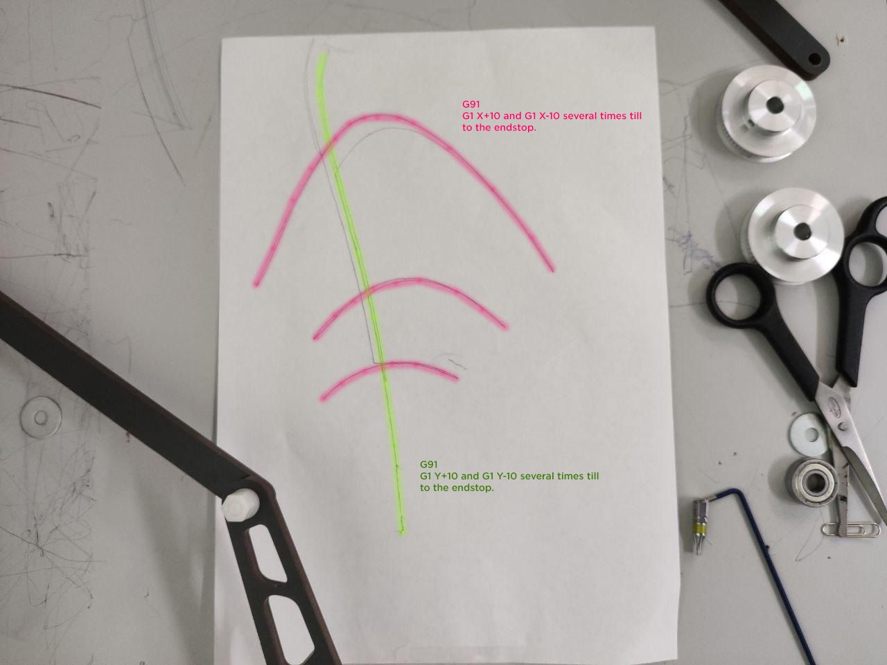
Homing went fine... G92 X0Y-250 After that G91 for relative positioning and then i go stepwise G1 Y+10 which creates that green line (can do it till i reach Y-30 then it tells me out of drawing area).... ok , its not perfect straight... but kind of
At 3 random points on the Y-Line I do several times G1 X+10 till endstop and several times G1 X-10 till endstop. This creates my pink lines and look like parabolas.When moving it looks like there is no loss of steps or friction.
Any idea why this is happening ? Is it bad configuration, bad hardware or maybe a failure in math fo firmware ?
I think as there is a trinsmission now that 71.1 steps / mm is too low now, could this cause this behavior ?I also attached my config.g
config.gBest,
Johannes -
@Enpixa said in Compiled Firmware with 5bar-Scara / Dual-Arm-Scara:
Is it bad configuration, bad hardware or maybe a failure in math fo firmware ?
I think as there is a trinsmission now that 71.1 steps / mm is too low now, could this cause this behavior ?If the firmware is know to work on another machine, then most likely bad calibration and/or incorrect steps/degree IMO.
-
@Enpixa I checked your config, I don't see an error.
Please tell me your stepper types (200 or 400 steps), pulley and big wheel teeth count, I'll setup the same configuration like you and process your tests.
-
@Enpixa , those bends moving along X sure looks like your steps/mm (actually steps/deg in this case) is wrong. The arms are in a totally different place than what the kinematics thinks.
Here is a very small google calc sheet to do the calculation: https://docs.google.com/spreadsheets/d/1BcMlqXXdEnmlkF_0ODQ4IW8XYK3qm9ZIXIymVJUUBbo/edit?usp=sharing
-
Hello All,
I disassembled the prototype and checked the steppers. It needs 200 steps per Revolution
( checked it by setting microsteps to Fullstep (1) and set it to 200steps per mm )
M350 X1
M92 X200
and did a G1 X1 and it was exactly on complete Turn for the stepper. (Did the test for both Steppers to be sure)Small Pulley got 20 teeth. large Pulley got 90 teeth.
I used Bondus formula-Sheet and came to 320steps
Part of Config.g
;---------------- AXIS LIMIT ---------------------------------------
M208 X-1300 Y-1300 Z-1000 S1 ; Set axis minima
M208 X1300 Y1300 Z1000 S0 ; Set axis maxima;---------------- MAIN SETTINGS -------------------------------------------------------
M669 K9 L2 X0:70 Y0:0 P262:262 D262:262:40:0 B143:37 A10:170:0:360:0:360 C-90:270:-90:270
M350 X128 Y128 Z128 E16 I1 ;S3 ; Configure microstepping with interpolation
M92 X320 Y320 Z320 E95.2 ; Set steps per mm*used this home5barscara.g
G91 ; relative positioningG1 H1 X-500 F1000 ; move quickly to endstop and stop there (first pass)
G1 H1 Y500 F1000 ; move quickly to endstop and stop there (first pass)G92 X0
G92 Y-285
G92 Z0
When i run this simple Square.gcode
G1 X30 Y-160 F2000
G1 X30 Y-160 F2000
G1 X30 Y-100 F2000
G1 X-30 Y-100 F2000
G1 X-30 Y-160 F2000i get this result:
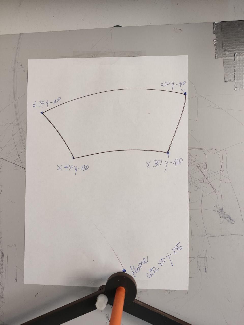
It seems like i get some kind of 2:1 ratio for X:Y ( Did a different test with Moving G1 Y100 it was about 10cm and Moving G1 X30 was about 6cm )
Also this "Square" looks like a 2:1 rectangle (some kind of :))
:))I am not sure about the Home5barscara value for the G92 Y ( tried many different. often gives me not reachable area when starting from different Y-Positions. When homed the hotend-spot is 285 mm away from the Rods along Y-axes.
Also tried instead of M669 K9 L2 X0:70 a different version with M669 K9 L2 X-32.5:32.5 (measured again it is 65mm apart) the "rectangle was centered better to the X-Homepoint but basically the same result. Also checked the angle of the arms again when homed. B143:37 ( i think this should sum up to 180 as it is symmetrically on X,please let me know if i am wrong )
-
@Enpixa said in Compiled Firmware with 5bar-Scara / Dual-Arm-Scara:
G92 X0
G92 Y-285I did a quick test, and as I suspected the kinematics does not handle G92 X and Y as expected. Try removing them from your homing script. Keep the G92 Z0. The firmware will calculate X and Y of the actuator on it's own. If you want to move the world coordinates X0 Y0 use M669 X and Y to move the inner proximal joints instead .
This might bug in the kinematics, I'm not sure how the firmware kinematics is supposed to handle this. It could be that the non-linear kinematics, deltas and scaras, assumes that you have actually moved the motors to the position given in G92.
And BTW, Y coordinates are positive towards the front of the machine (the arm side). Your G92 Y-285 told the machine it's arms were on the backside. The, in practice unreasonable, work mode 2 position for that would be:
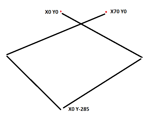
It's a fun kinematics
-
Hello Bondus,... thx alot.....
i removed the G92 X & Y from home5barscara.gcode
and changed in config.g to:
M669 K9 L2 X-32.5:32.5 Y285:285 P262:262 D262:262:25:0 B143:37 A10:170:0:360:0:360 C-90:270:-90:270
in that case, as i would expect to be a "normal" situation, -X moves left and +X moves right (looking from steppers in direction to hotend) and +Y moves the hotend away from stepper. But doesnt solve the problem. Still looks like a 2:1 ratio.
If i negate the M669 Y Value (to -285:-285) the directions of the whole machine invert.
Maybe this information helps to find what is causing the problems
-
@Enpixa , I think your motors run in the wrong direction. Looking at your homing file I see that you home X(left arm) using a move towards negative, but that arm homes at a big angle. Same for Y, but opposite.
Modify your M569s and the homing file. -
@Enpixa I am confused why you set Y285:285, this sets your actuators into the print bed.
-
@Enpixa I will setup my Scara with your parameters at the weekend, please tell me which configuration you have right now und the G-Code of your test "prints".
-
Here are some parts of my configuration file if it helps:
M350 X128 Y128 Z16 E16 I1 ; Configure microstepping with interpolation ; Left homes at 180deg, Right at 0deg M669 K9 X-93:93 Y-205:-205 L2 A10:170:0:360:0:360 C-90:270:-90:270 P134:134 D205.00:205.00:0:0 B180:0 ; Old machine, more sensible limits. Right homing sensor is between arms ; M669 K9 X-54:54 Y-192:-192 L2 A10:170:-90:360:-90:360 C34:251:-71:146 P161.00:162.00 D206.00:208.00 B226.01:152.21 ; 400/360 * 128 * 263 / 16 M92 X2337.777778 Y2337.777778 Z800.00 E420.00 ; Set steps per mm/deg, 128micro ; Axis Limits M208 X-350 Y-350 Z0 S1 ; Set axis minima M208 X350 Y350 Z188.2 S0 ; Set axis maxima M569 P0 S1 ; X Drive 0 M569 P1 S1 ; Y Drive 1 -
@bondus Thank you.
I changed the documentation by some of the items discussed here. After resolving this issue here I want to implement work mode 3 also, and I am looking for a solution how to change work modes automatically.
-
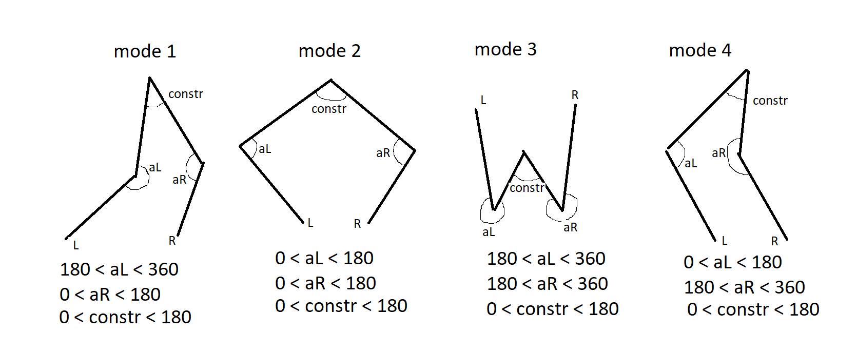
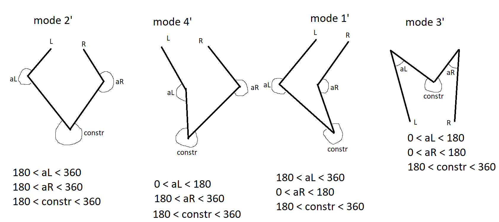
@JoergS5 Work mode 3 is implemented. It is a pretty strange work mode, you will need very specialised arm lengths to get any reasonable work space.
I tried work mode 1 and 4 or my new machine yesterday, they work perfectly fine.
I experimented a few weeks ago with some work mode switching on a toy scara machine run by a Teensy board. I had copy-paste ported our code to run outside RRF.
I think that switching can safely be done if done in the right order. Mode 1 can move to mode 2 or 3, mode 2 can move to mode 1 or 4, mode 4 can move to mode 1 or 3. Basic rule is that if you flip one proximal-distal arm joint at a time it will be safe. By flip I mean to change from the range 0-180 deg to 180-360 deg.
The work mode switching order would be 1-2-4-3-1-... , any direction is allowed.Exactly when, how and why to do a switch I'm not sure. Except that it's fun.
If you want to be very brave and flip the actuator joint with a dynamic move that's a very different story
") The firmware does not support the other 4 work modes you have on the other "side".
The firmware does not support the other 4 work modes you have on the other "side".I'll dig up some old pics I made a long time ago ...
-
@bondus I expect work mode 3 not supported because in the source for L:
if (!(workmode == 1 || workmode == 2 || workmode == 4))
{
error = true;
return true;
}so for workmode == 3 will be an error. (My fault, I excluded it, because of missing testing).
For changing work modes, my thoughts are:
every workmode has a safe print area which can be defined for given allowed angles and arm lengths. When changing work mode, a moving path through overlapping areas is a safe path. Moving without printing is safe, but printing while changing workmode is unresolved (the print move must be splitted, either from firmware or in the G-Code). When changing the workmode, all singularity areas must be avoided.My wish to use workmode 3 is:

below = below printbed, above = above, perpendicular = steering bars.
The reason is to save space in x-y dimension.
(To explain: perpendicular is not the proximal arm, but a vertical bar, rigidly connected to the distal arm. The proximal arm is the big plate with a ball bearing inlcuded at the edge. The big plate get a 1:30 gear ratio with the stepper)I want to include your formula and spreadsheet for calculating the stepper setting into the documentation, I'll do that in the next update.