Five bar parallel Scara
-
Just missing two endstops and an extruder and it's ready to go.
I spent hours calibrating it yesterday. Since nothing is really adjustable that meant filing on plastic pieces and very slightly bending and twisting the arms.
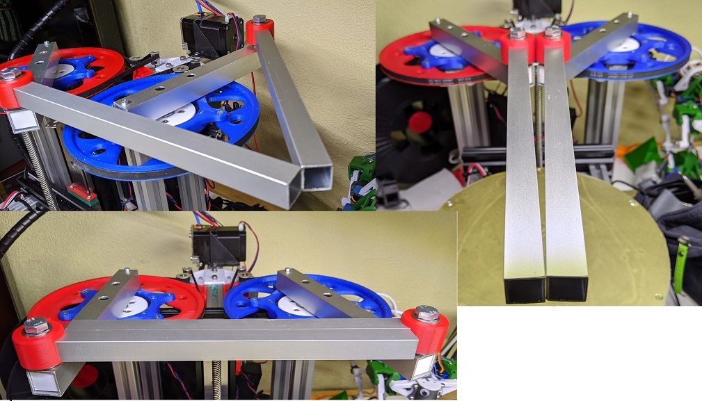
It is critical that all joint bearings work in the same plane, it is an overconstrained system in the z-plane. If not all 5 joints are in the same plane they will fight each other and create a strange z-deviation map.
Any errors can easily be seen by keeping the actuator at the same spot but changing the arms to different work modes.I'll put adjustable endstops at right angles, 0deg for right arm and 180deg for left arm. That way they are easy to calibrate.
Possibly they are better placed straight back if I will use work mode 1 or 4. It can be a bit tricky to home the machine from an unknown position. -
After some quick tuning of the hotend and more mechanical calibrations I managed to print this stunning benchy, at 120mm/s and 2500mm/s^2 acceleration. I'm surprised!

-
Some videos of the beast in action:
Printing of a calibration item at 120mm/s.
https://youtu.be/yubS3_OUhQsSame thing but in a different work mode (arms at a different angle). I have tried to make this machine as flexible as possible to be able to test all cases of the firmware. If I extend the outer arms a little bit the inner arm can travel all the way around to the backside. Right now the hotend collides with the pulleys.
https://youtu.be/1IpzSe83RkQ -
@bondus Thanks for sharing the videos. Good idea to make the proximal inner arms shorten than the actuator difference. My arms are longer and I have some problems (I support the axes at the top with a bridge and the arms are in the way).
What do you mean by "hotend collides with the pulleys". At which time?
-
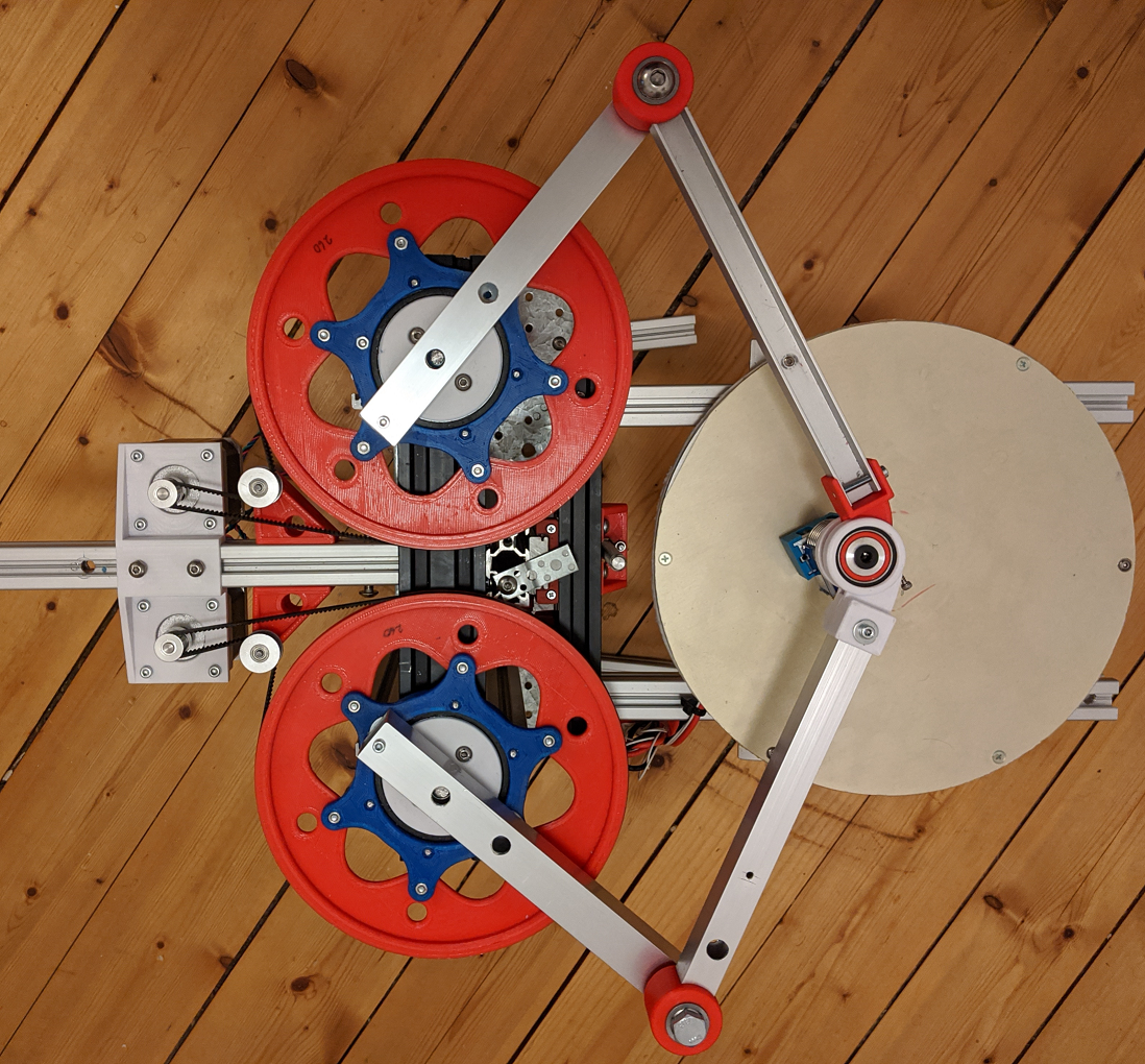
@JoergS5 The short proxial arms have the drawback that it gets quite a small reach. It could be made better by putting one of the proxial arms a bit higher up to not collide with the other one, and make it longer. It would work good for work mode 1 or 4 depending on which arm is longer.
It's hard to pick arm lenghts that are good for everything. And it's hard to avoid colliding with something, other arms, the frame, motors ...The hotend collides with the pully if the proximal arm points straight back and the distal arm points forwards, or if both proximal arms points too far to the sides. It has a tendecy to do that when I home it. Homing only works reliably if it starts with the proximal arms pointing forwards. I need a low resolution absolute encoder to be able move the arms in a safe way to the homing endstops.
The distal arm just needs to be around 20-25 mm longer to make many more moves possible.
It is possible to move the hotend to the backside if you navigate it on the side around the pulleys. I should handcraft some gcode to show off what kind of moves it is capable of, it is very flexible.
-
@bondus Thanks for explaining. I once had the idea to design variable arm lengths and actuatuar difference and decide from the object-to-print which configuration to use: print area ok, configuration so that the goal is reached to have maximum precision or speed. Maybe I come back to this idea (telescopic arms?).
-
@bondus If you want to improve your hinges between proximal and distal arms, you can consider using bigger support surfaces. I think this is the reason why the commercial robots have such big diameters of their hinges (or Mitsubishi RP series). For low friction between surfaces/washers, PTFE on PTFE has low friction.
-
I have had some more adventures in calibration, the grid test model is almost 100% correct now.
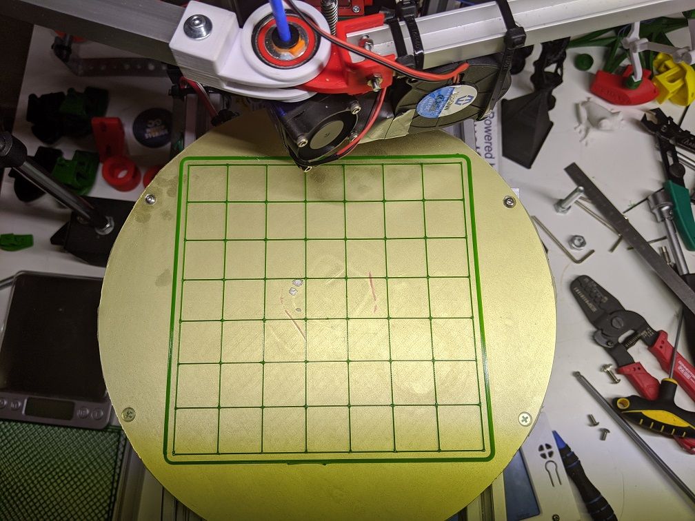
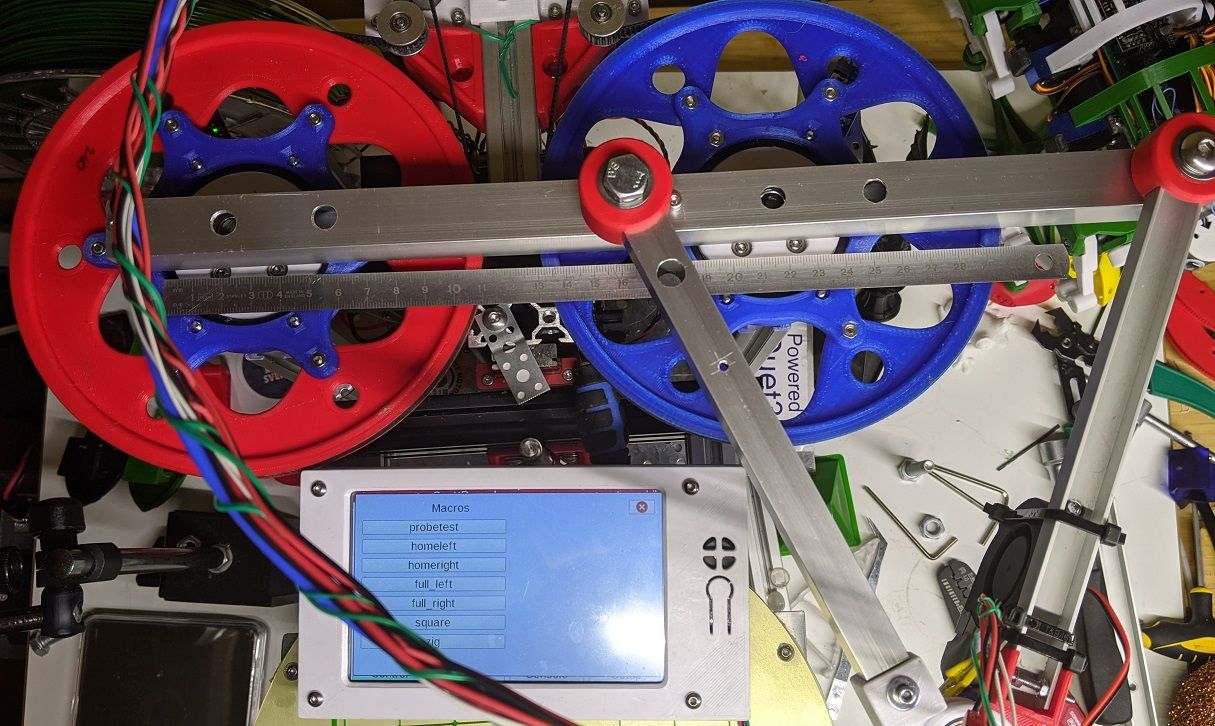
One of the trickiest parts to calibrate on a rotating machines are the angles. I had that in mind when designing this machine and made sure that it would be reasonably easy to measure critical angles. The key trick is that the homing positions are at 0 and 180 degrees, and that the inner arms can be lined up. Simply using a straight ruler and a few GCODE macros the errors can be measured and homing positions and steps/deg can be adjusted. It is very important that the angles are correct within about 1%% or there will be large errors in the cartesian space at some positions.
The trusty old dial gauge has had it's uses too making sure the pulley are centered and round:
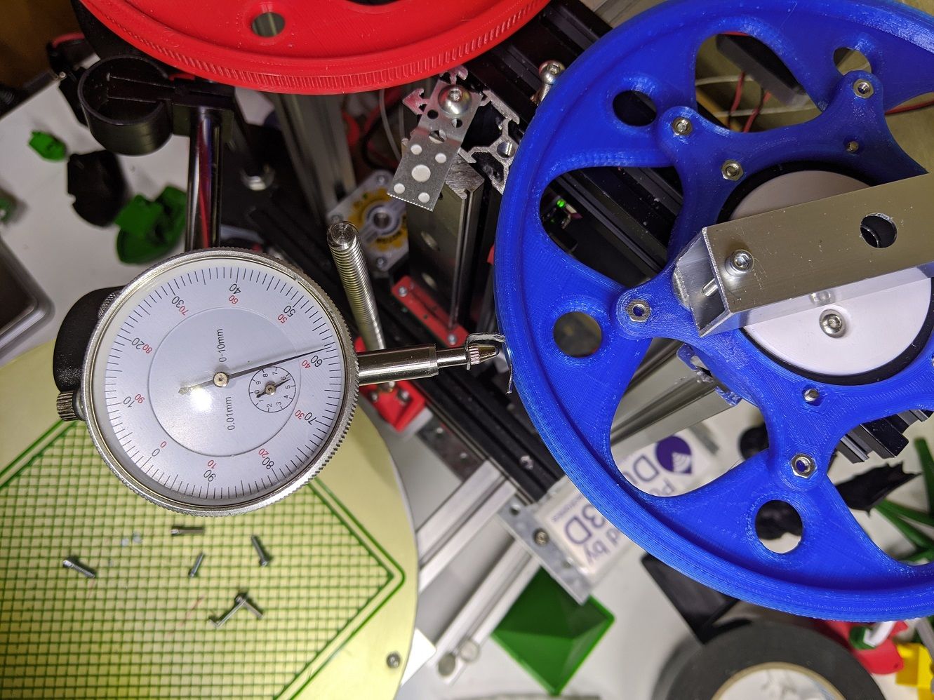
The real world steps/deg was off by over 1% from the calculated ideal. I'm not sure if it is my printed pulleys or the generic 16t chinesium pulleys on the motors that are to blame.
It took a few tries to get the printed pulleys working right, shaving off 0.1mm on the tooth surfaces made it properly sized. Fortunately the belt will not teeth properly if it is too big or too small, instant verification of tolerances.
I should create a test model that can be printed, measured and fed into a program to do the calibration instead. The math for this is non-trivial though, there are lots parameters to tune. Some kind of numerical solving algorithm would probably be needed. It would be a lot more user friendly though.
-
@bondus you're a little ahead of me, but I'm catching up!
")
I want to measure angles by an optical encoder attached to the big wheels, which has higher precision than to measure at the steppers imho. But I start with a normal endstop also, attached to the big wheel.
To avoid backlash at the pulleys or hinges, I want to try a spring that pulls the axle to one side.
-
@JoergS5 said in Five bar parallel Scara:
If you want to improve your hinges between proximal and distal arms, you can consider using bigger support surfaces.
The current solution in the "elbows" with a heavily preloaded thrust bearing to do most of the work works very well. The thrust bearing actually does the radial load as well as the axial load, and it's the friction between the bearing house and the arms that holds everything in place! The printed parts is holding the thrust bearing in place, but plastic is soft.
A mechanical engineer would definitely not approve of this solution. But it works and it's a very simple and compact solution.And bigger is better for sure. I used 8x16 bearings before, now they are 10x18.
-
I am still shocked with the quality of the prints this machine can produce. It beats my CoreXY machines and is almost on par with the delta.
Apart from the need for better cooling and extrusion control (not the focus of this project) this dragon looks amazing. I hold it in a light to show the flaws as much as possible.
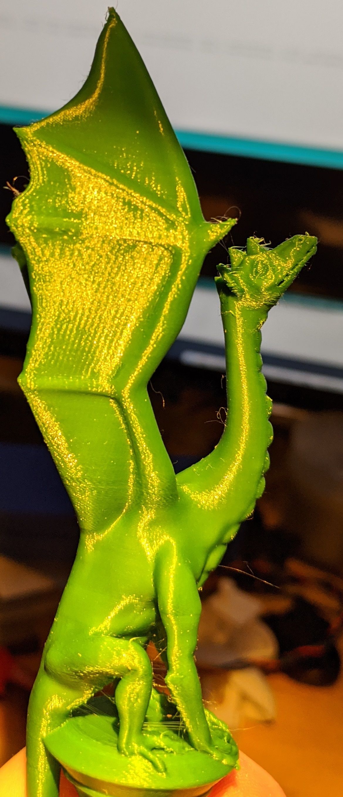
There is a very small amount of ghosting and some strange visible lines.
I think these lines are an stepper artifact, the gearing of the arms are still on the low side.
My delta machine (not duet but TMC drivers) have similar patterns but not as visible.

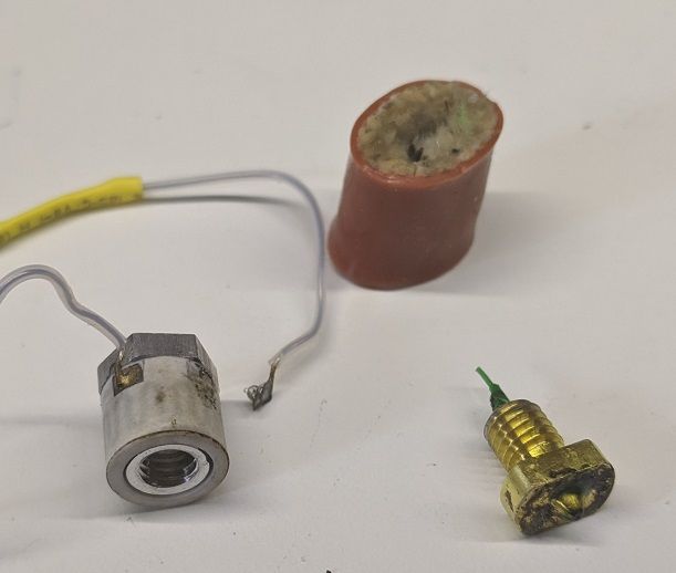
I managed to break my last ceramic heatblock, a fragile construction. And they stopped producing those
 They were amazing, heated up in 20s and could handle high flows. The RRF PID tuning used to warn that "ultimate temperature" was unsafe when auto tuning
-
@bondus I have an idea how to calibrato 0 and 180 degrees exactly:
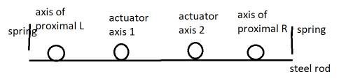
from above. The steel rod defines a line for 0 and 180 degree. Electric circuits (2 for testing 0 and 180 separately) of arm and axis are closed if 0 (or 180) not reached, and go open when endstop reached. After defining the endstops, the rod must be removed to not disturb if <0 and >180 shall be reachable. -
@JoergS5 That's not a bad idea! A very simple little contraption. If the bolts through all axis are the same dimensions you could use those as they are. With some clever isolation on the steel rod and some crocodile clips to the bolts...
I hacked together some GCODE to show off what the machine can do. Speed and agility: https://youtu.be/hhD8bg6w6lo
It starts losing steps over 6000mm/s acceleration
-
@bondus Nice speed. I have good speed even with my 1:30 gear. Your moves outside the print area are valuable for tool changers.
-
@bondus did you see you made it to Hackaday?! https://hackaday.com/2020/03/18/a-practical-dual-arm-scara-3d-printer/
Ian
-
Oh! Hackaday! I'm famous!
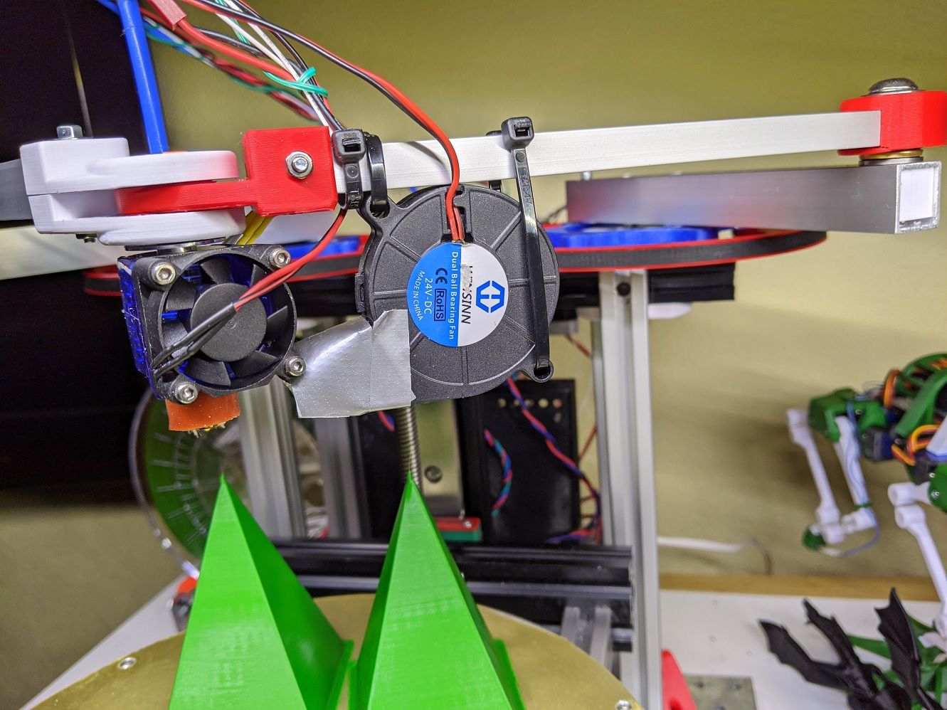
I spent a few hours being confused in Fusion 360, and eventually managed to make this manifold fan duct for parts cooling. It seems to work ok. But cooling PLA at 120mm/s is not easy.
That "transparent" PETG makes everything you print in it look horrible.

-
I have tried to tune this beast for a while now to be good at general printing. But that long bowden tube is hard to tame.
Others seems to be ok with this, I can't do it. Always plastic where you don't want it or nozzle clogs.I made my delta flying extruder and my CoreXYs direct or nimble.
A direct drive is minimum 300g, which is a bit heavy for this mechanics to carry in the z axis.
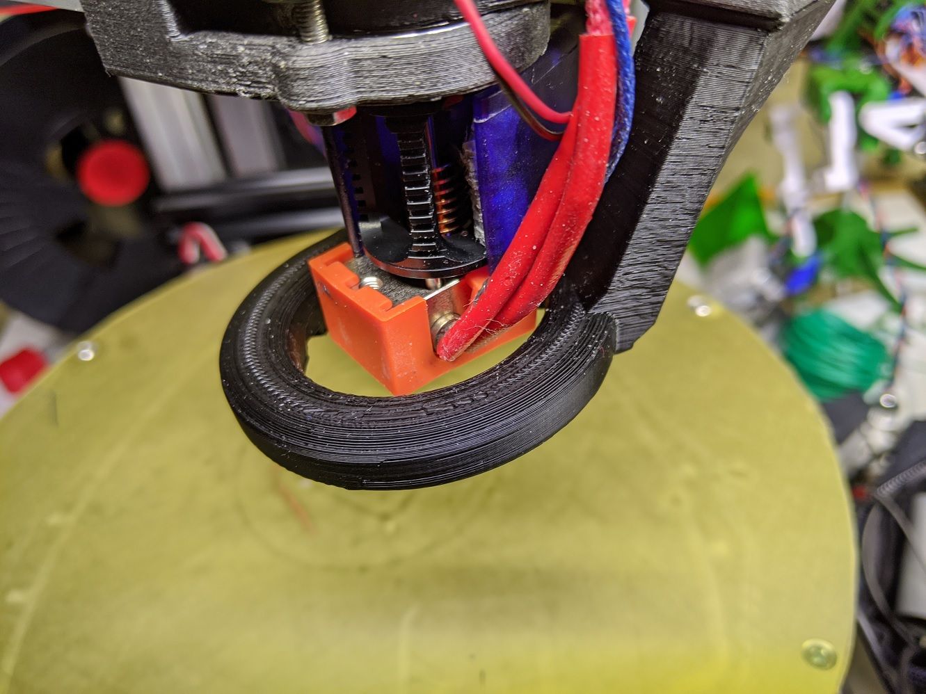
And what is the consensus for a good part cooler? My homemade ring cooler does not work very well.
-
@bondus said in Five bar parallel Scara:
And what is the consensus for a good part cooler? My homemade ring cooler does not work very well.
Need a good radial blower with enough static pressure to work well with a duct like that.
-
if you want to save a bit on a direct drive weight, you can look at what the Voron people did for their newly released Voron0: Go Nema14 on all steppers. They released a shrunk version of the BMG design that fits on a Nema14 stepper. You save about 80g compared to a Bondtech with a Nema17 with enough torque.
-
A hint for everyone building a parallel scara:
Before mounting the head move the arms around in all kind of strange positions and make sure that the distal arms are at the same height (or at the offset you designed them to have). Especially try to reach the same spot with different arm-angles. If they do not line up everywhere it will be impossible to get flat XY movement in the z-plane.
It can be quite a lot of work to get it all right but it is at the same time a kind of self-verification of the machine that all joints rotate perpendicular to the same plane. A very nifty feature.
I had to use a mixture of gentle filing on some plastic pieces and brute force bending and twisting the aluminium tubes to get this machine straight. Alu-extrusions from the local hardware store are not made for precision machinery.