Nozzle probes off bed.
-
Looks like you should start with reading these:
https://duet3d.dozuki.com/Wiki/Bed_levelling_using_multiple_independent_Z_motors
-
@Borgtribble said in Nozzle probes off bed.:
I read somewhere that the machine will not run the m557 file if there's bed.g file present.
No, that's not the case.
bed.g is a macro that gets called by G32.
Mesh compensation using M577 grid parameters is called by G29.
The two are otherwise unrelated.
-
G30 P1 X0 Y17will send the nozzle to that point, not the probe. so if you have an x probe offset of -2, then it'll be -2 off the bed at that point.
-
@Turbo Thanks for the help! Ok so I narrowed it down to the x offset. When define the probe X-48 then set the mesh for X48:200 it should start at X0 and work across correct. The printer always starts at X48 even with I set X0:200. The only time it will start at X0 is when I have probe offset set to 0 and mesh X0:200.
-
EDIT: completely ignore this. i mightve mixed up my info
im gonna test some stuff on my printer. for now, whats your bed size?your x offset is -48, so the minimum you can probe is 48 in the x direction. 48:200 should work. this should put the probe where normally the nozzle would be at (0,0). Its always going to start at x=48 even with 0:200 because the probe cant probe anything at where x=0, because that would set the probe 48mm off the bed.
The points are defining where the nozzle will be when it is probing, so while your nozzle is at (48,2), and thats what your GUI says, in reality your probe would be at 0,0, because of its offset to the nozzle.When you say you start it at X0, do you mean probing or Printing? and if youre starting at X0, isnt the probe off the bed? Maybe I'm missing something.
Cant stop tuning wont stop tuning.
Dbot, Custom i3, Voron 0&2 -
@Borgtribble
Yea i got it backwards. From the website (when referring to M557:
"The second form defines the grid for G29 bed probing. For Cartesian printers, specify minimum and maximum X and Y values to probe and the probing interval. For Delta printers, specify the probing radius. If you define both, the probing area will be the intersection of the rectangular area and the circle. There is a firmware-dependent maximum number of probe points supported, which may be as low as 100. "So in your case, if I got it right this time, it would be:
M557 X0:172 Y0:220 S:43:55;Make sure you're using G29 in your slicing settings to do mesh bed leveling.
Cant stop tuning wont stop tuning.
Dbot, Custom i3, Voron 0&2 -
@Turbo bed is 220 220 250 , you can go as high as 235 ish on both x and y.
-
@Turbo The bed pick is perfect if you flip it so the offset volume is on the left when facing it.
-
@Turbo OK my bad, setup calls for a - 48 (which going through the many configurations of petsfang I found this -->>Right BLT...............................X....+48................Y.....-2) which should be positive 48. So by switching the - to a + the machine works with my setup now, just the points are not in a clockwise rotation. (For note I did switch the - to + but I posted here, but at that point I had other issues causing the problems.) SOOOOoooo this is my new offset xy bltouch bedmesh
225-48=177-2(-2 for bedstartpoint)=175/5 =x35
227-2=225-15(-15 for bedstartpoint)=210/5 =y42G31 P25 X+48 Y-2
M557 X2:177 Y15:227 S35:42This will give me a 5x5 which I need to map out in a ccw pattern. What changes do I need to make to my bed.g file? I found this on the forum
""1. A sequence of 3, 4 or 5 G30 commands with coordinates. This is the old way of doing it. You are limited to just 5 points, and you can specify trigger height corrections for those points.
- A G29 command to do mesh leveling. You don't get to choose individual points (just the grid) and you can't specify trigger height corrections. But you can have a lot more points.""
If I'm running 25 point check I need to delete out the old G30 command lines and replace it with a G29?
-
@Turbo ALL FIXED got it working so I'm all good! I'm using G29 in the bed.g and got the first bed mesh mapped out. Currently my resin printer is making a mount to go on the left side. This will allow me to probe more of the bed :). I learned quite a bit since I botched this probe offset, with the new knowledge I plan on make the best bed mesh I can. Again thanks for all the help everyone, and Turbo you did a lot here so I'm going to name my Printer "Turbo" (Hopefully no more issues from here!)
-
Glad you got it! Its really weird at first, but it makes a lot of sense when it clicks ya know. If youve got any more issues lemme know
-
@Turbo Thanks, I'm hoping with the touch mounted on the left I can get most of the bed mapped out. (Since the probe can move more to right of the hotbed)
-
Can anybody explain how to do the above when you’re bed origin is at the Centre?
I’m using a induction sensor with a special print bed top. My printer is an Ender 5 pro, with a duet 2 maestro board.
My probe offset is -60(x) and -12(y).
What’s the formula you should use to figure out what to program your settings to so my probe doesn’t go off the bed?
Thank you so much for your hell with this!
-
@Damien it should be very much the same since it's still just a cartesian X Y coordinate system. The only difference with having 0,0 in the center is that the low ends will be negative.
What are your M208 limits?
-
@Phaedrux right now it’s
M208 X-110 Y-110 Z0 S1
M208 X110 Y85(Due to the HeroMe Gen5 duct installed) Z300 S0 -
I was thinking of putting together an Excel Spreadsheet and sharing it so it figures out min/max values automatically.
Thank you for your help, by the way!

-
Alright, so the M557 would as far as you want on the low side because your probe offsets are to the low side, and on the high side it would only be able to reach as far as x110 - x60 and Y85 - y12
-
@Damien The easiest way to find the ideal M557 for me in practice is to just jog the print head around so that the probe is where I want it and take those XY coordinates.
-
Ok....I am still so confused!

So I took you suggestion about jogging head around to find what I can work with based on my mods.
As a result, my min/Max axis has changed.
Below is my config. What calculations should I use to figure out how to define the grid again?

Thank so much in advance!!
; Configuration file for Duet Maestro (firmware version 3)
; executed by the firmware on start-up
;
; generated by RepRapFirmware Configuration Tool v3.1.3 on Sat Jun 13 2020 22:55:16 GMT-0500 (Colombia Standard Time); General preferences
G90 ; send absolute coordinates...
M83 ; ...but relative extruder moves
M550 P"Damiens Ender 5 Pro" ; set printer name; Network
M552 P0.0.0.0 S1 ; enable network and acquire dynamic address via DHCP
M586 P0 S1 ; enable HTTP
M586 P1 S0 ; disable FTP
M586 P2 S1 ; enable Telnet; Drives
M569 P0 S1 ; physical drive 0 goes forwards
M569 P1 S1 ; physical drive 1 goes forwards
M569 P2 S0 ; physical drive 2 goes backwards
M569 P3 S0 ; physical drive 3 goes backwards
M584 X0 Y1 Z2 E3 ; set drive mapping
M350 X64 Y64 Z64 E128 I1 ; configure microstepping with interpolation
M92 X320.00 Y320.00 Z3200.00 E747.59 ; set steps per mm
M566 X900.00 Y900.00 Z60.00 E600.00 ; set maximum instantaneous speed changes (mm/min)
M203 X6000.00 Y6000.00 Z300.00 E1500.00 ; set maximum speeds (mm/min)
M201 X500.00 Y500.00 Z100.00 E5000.00 ; set accelerations (mm/s^2)
M906 X800 Y800 Z800 E800 I30 ; set motor currents (mA) and motor idle factor in per cent
M84 S30 ; Set idle timeout; Axis Limits
M208 X-110 Y-110 Z0 S1 ; set axis minima
M208 X105 Y92 Z300 S0 ; set axis maxima; Endstops
M574 X1 S1 P"xstop" ; configure active-high endstop for low end on X via pin xstop
M574 Y1 S1 P"ystop" ; configure active-high endstop for low end on Y via pin ystop; Z-Probe
M558 P5 C"!^zprobe.in" H5 A1 F120 T6000 ; set Z probe type to switch and the dive height + speeds
G31 P200 X-60 Y-12 Z5.98 ; set Z probe trigger value, offset and trigger height
M557 X-110:110 Y-110:110 S10 ; define mesh grid; Heaters
M308 S0 P"bedtemp" Y"thermistor" T100000 B3950 ; configure sensor 0 as thermistor on pin bedtemp
M950 H0 C"bedheat" T0 ; create bed heater output on bedheat and map it to sensor 0
M143 H0 S120 ; set temperature limit for heater 0 to 120C
M307 H0 A140.3 C627.1 D0.2 S1.00 V22.9 B0 ; disable bang-bang mode for the bed heater and set PWM limit
M140 H0 ; map heated bed to heater 0
M308 S1 P"e0temp" Y"thermistor" T100000 B3950 ; configure sensor 1 as thermistor on pin e0temp
M950 H1 C"e0heat" T1 ; create nozzle heater output on e0heat and map it to sensor 1
M143 H1 S280 ; set temperature limit for heater 1 to 280C
M307 H1 A340.0 C140.0 D5.5 S1.00 B0 ; disable bang-bang mode for heater and set PWM limit; Fans
M950 F0 C"fan0" Q500 ; create fan 0 on pin fan0 and set its frequency
M106 P0 S0 H-1 ; set fan 0 value. Thermostatic control is turned off
M950 F1 C"fan1" Q500 ; create fan 1 on pin fan1 and set its frequency
M106 P1 S1 H1 T45 ; set fan 1 value. Thermostatic control is turned on
M950 F2 C"fan2" Q500 ; create fan 2 on pin fan2 and set its frequency
M106 P2 S0 H-1 ; set fan 2 value. Thermostatic control is turned off; Tools
M563 P0 D0 H1 F0:2 ; define tool 0
G10 P0 X0 Y0 Z0 ; set tool 0 axis offsets
G10 P0 R0 S0 ; set initial tool 0 active and standby temperatures to 0C; Custom settings are not defined
; Miscellaneous
M575 P1 S1 B57600 ; enable support for PanelDue
M501 -
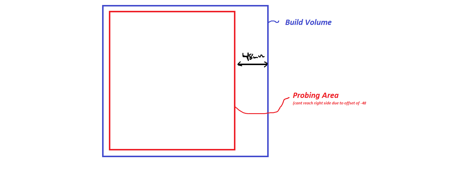
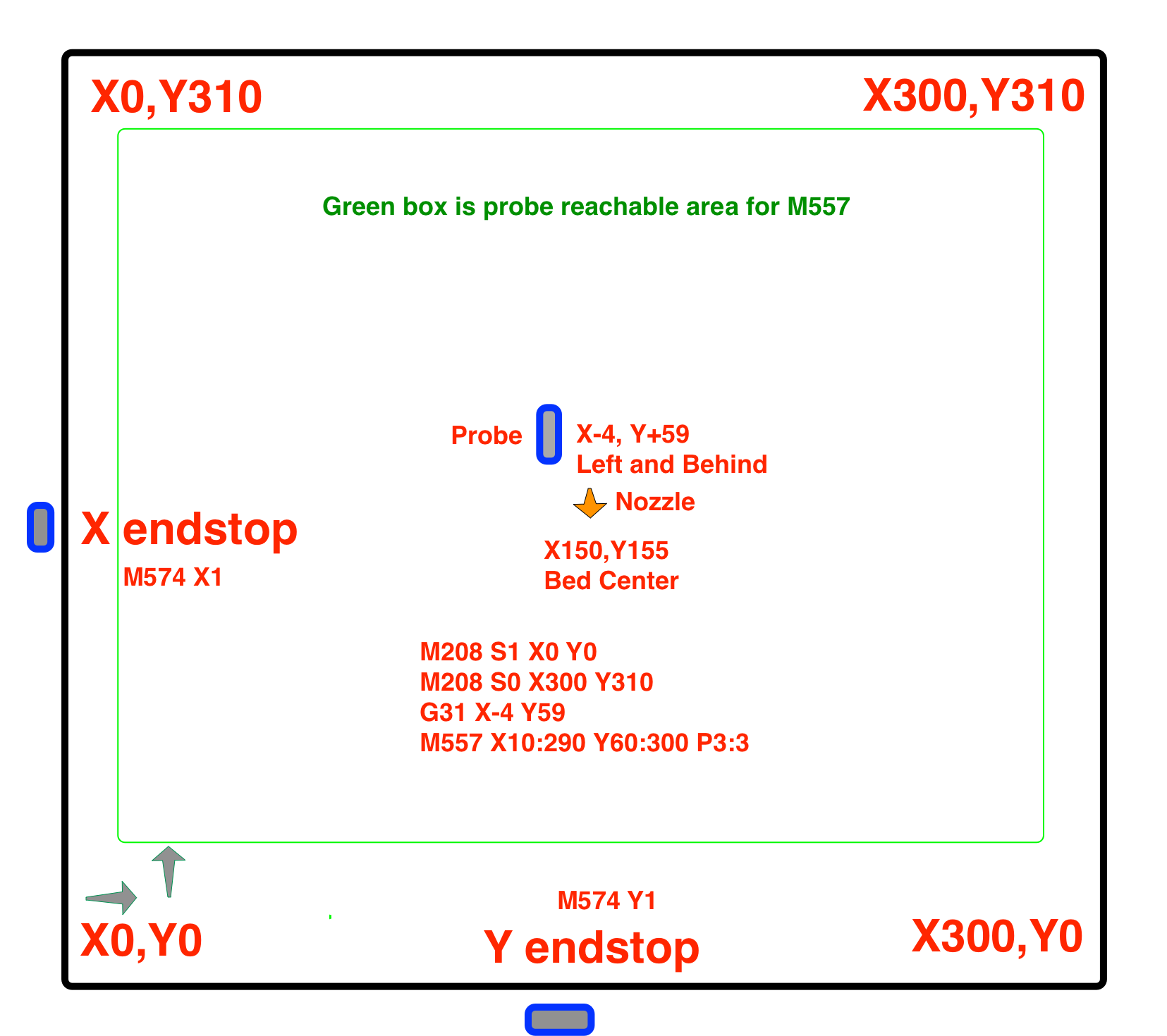
Maybe it would help if you created a diagram of your bed like this one.
By the way, 60mm in the x direction is quite a bit. Is that really the closest you can get the probe to the nozzle?