How to compensate for X/Y dimensional errors?
-
I am trying to calibrate the X/Y dimensions of my prints on my HEVO corexy.
To do so, I printed an object with measurable dimensions in 10mm increments and measured the actual dimensions. I printed it diagonally on the bed such that the measured dimensions are affected by only a single corexy stepper.
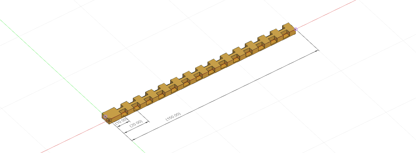
The results of the actual vs expected dimensions and a linear fit are in this graph, generated by a spreadsheet:
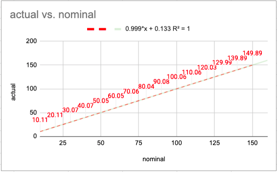
This gives two numbers: scale is 0.999 and offset is 0.133mm so the questions is how to I compensate for these values? For the scale of 0.999, I think I need to change my M92 command from Y200.00 to Y200.2.
M92 X200.00 Y200.00 Z400.00 E830.0 ; Set microsteps per mmWhat should I do about the 0.133mm offset which seems to contribute the main error? The only thing I can think of is setting my slicer to inset X/Y by 0.133mm/2 (X/Y size compensation in PrusaSlicer), assuming that the other corexy stepper will give the same offset.
-
As you suggested, change your steps/mm. As you pointed out, it accepts decimal fractions.
-
Please post at least these sections of your config.g:
; Axis to driver mapping
M584 X0 Y1 U2 Z3:4:5        ; X and Y for CoreXY.  U for toolchanger lock. Z has three drivers for kinematic bed suspension.
M584 E1.0:1.1:2.0:2.1       ; Extruders for four tools.

M569 P0 S0                  ; Drive 0 direction | X stepper
M569 P1 S0                  ; Drive 1 direction | Y Stepper
M569 P2 S0                  ; Drive 2 direction | U Tool Changer Lock
M569 P3 S0                  ; Drive 3 direction | Front Left Z
M569 P4 S0                  ; Drive 4 direction | Front Right Z
M569 P5 S0                  ; Drive 5 direction | Back Z
; End of main board drivers.  Expansion boards have three each.
; Expansion 0
M569 P6 S0                  ; Drive 6 direction | Extruder T0
M569 P7 S0                  ; Drive 7 direction | Extruder T1
; Expansion 1
M569 P8 S0                  ; Drive 8 direction | Extruder T2
M569 P9 S0                  ; Drive 9 direction | Extruder T3

; Kinematics
M669 K1                                 ; CoreXY mode

; Leadscrew locations (really, kinematic coupling locations) extracted from CAD model assuming back right build plate corner is (0, 0)
M671 X300:5:152.5 Y316:316:-14 S10 ; Front Left: (300, 316) | Front Right: (5, 316) | Back: (-14, 152.5)

; Axis and motor configuration
M350 X16 Y16 I1                   ; Set 16x microstepping for axes. Use interpolation.
M350 U4 I1                        ; Set 4x for toolchanger lock. Use interpolation.
M350 Z16 I1                       ; Set 16x microstepping for axes. Use interpolation.
M350 E16 I1

M906 X2000 Y2000 Z1000 E1250 I30        ; Motor currents (mA) and Idle percentage
M906 U1100 I40                          ; Motor currents (mA) and Idle percentage
M201 X600 Y600 Z10 E1000 U1000          ; Accelerations (mm/s^2)
M203 X25000 Y25000 Z400 E4000 U10000    ; Maximum speeds (mm/min)
M566 X700 Y700 Z2 E3000 U200          ; Maximum jerk speeds mm/minute

;M92 X200 Y200                           ; Steps/mm for X,Y with 16 tooth pulleys (preferred).
M92 X160 Y160                           ; Steps/mm for X,Y with 20 tooth pulleys.
M92 Z3200                               ; Steps/mm for Z - TR8*4 / 0.9 deg stepper
M92 U11.429                             ; Steps/mm for tool lock geared motor.
M92 E837                                ; Extruder - 0.9 deg/step
Delta / Kossel printer fanatic
-
The data is based on your measurements with a caliper. Notice that the first couple measurements (around 10-20 mm) are the worst. When you measure things with a caliper, there is always some error on the part of the person doing the measuring. Maybe you didn't hold it perfectly square maybe you pushed harder on the caliper and caused it to flex or the object being measured to compress, etc. For small measurements, the error makes up a larger part of the reading. This is why all those 20 mm "calibration cubes" that people keep printing are just silly. If you base your settings on a 20 mm measurement, when you print something larger the absolute error will multiply. The percentage error remains constant, but in the real world, where parts have to fit together, the absolute error is what counts.
If you ignore the first couple measurements, the others are pretty close. Maybe as close as variations in filament diameter and nozzle hole roundness will allow. Once the molten plastic leaves the nozzle, it does what it wants until it cools enough that it can't.
-
@mrehorstdmd said in How to compensate for X/Y dimensional errors?:
when you print something larger the absolute error will multiply.
It depends what is the model of the error just (measured = A x expected), or (measured = A x expected + B). The fixed error B can occur for example due to extrusion width wider than expected.
Anybody can comment of the proper error model for 3D printers?
-
@Danal said in How to compensate for X/Y dimensional errors?:
Please post at least these sections of your config.g:
My config.g is here https://github.com/zapta/misc/blob/master/hevo/duet/sys/config.g . The printer is a corexy, 0.9degree steppers, 16T pulleys, 2mm pitch GT belts.
-
Nonono! Dont change your steps/mm. The steps/mm should only be based on the machine. Take your caliper, drive one axis 100mm and check how much it´s traveled. Based on this you should calculate your steps/mm.
If the part is too small you need to tinker with the scale and horizontal offset in your slicer.
Plastic shrinks, and you need to print it bigger for it to come out with the actual dimensions.
I see this error done a lot.
Here is quite a good video on it.
https://www.youtube.com/watch?v=0dFThbwAx2Y -
Your prints are within a few 10s of microns of the designed values. That's as good as you're ever going to get. It's a 3D printer squirting out molten plastic, not a cutting tool. If you need better accuracy than you're already getting, you'd better find some other way to make the parts that you're printing.
-
You know, I just really looked at the numbers in the first post.
150mm - 149.89 = 0.11
A 0.4 nozzle generally prints a line at LEAST 0.4 wide, quite often wider, depending on slicer settings. Most default to around 1.125 * nozzle width = 4.5. Therefore, this is about 1/4, or less, of a single line width. Which means it is WELL within measurement error.
I would not adjust anything based on this. Either print a much longer sample, or figure out how to measure your carriage movement with more than 0.01 accuracy and repeatability.
-
I'd suggest this has to do with shrinkage rather than steps/mm - but if you only print one type of filament then steps/mm will probably sort you out.
-
@bearer said in How to compensate for X/Y dimensional errors?:
I'd suggest this has to do with shrinkage rather than steps/mm
The shrinkage is proportional to the length of the object so is probably captured by the 0.999 scale error. It's a good point that I may also be able to compensate for it in the slicer.
The 0.13mm additive error seems to be something else since it is length independent.