Duet Maestro 2 stops mid print
-


The printer did print a few prints fine. Just randomly started to reset.
Here is what I've done so far today.
- I've rewired the printer completed. New connectors, new wires - No success.
- I've moved the location of the board to the bottom frame, as to reduce vibrations - No success.
- I've reformatted the sdcard - No success.
- I've created new gcode, Cura, Slic3r, PrusaSlicer. Fast, Slow. High, Low, whatever.. - No success.
- I've moved the X Limit switch from the gantry. - - No success.
- I've added a fan on the Duet. - No success.
Observations:
- Before the printer reset, the is definitely some weird printing going on... As if the g code is corrupt. I've noticed it on most of the fails.

- I have a good success rate, printing "longer" moves.. Like a base plate. But as soon as the detail start, and "movement - I might go for a while, of crash quick..

I'm really tired/frustrated

-
; Configuration file for Duet Maestro (firmware version 3)
; executed by the firmware on start-up
;
; generated by RepRapFirmware Configuration Tool v2.1.8 on Tue Mar 31 2020 16:02:15 GMT+0200 (South Africa Standard Time); General preferences
G90 ; send absolute coordinates...
M83 ; ...but relative extruder moves
M550 P"Cooper" ; set printer name; Network
M552 P192.168.0.9 S1 ; enable network and set IP address
M553 P255.255.255.0 ; set netmask
M554 P192.168.0.1 ; set gateway
M586 P0 S1 ; enable HTTP
M586 P1 S0 ; disable FTP
M586 P2 S0 ; disable Telnet; Drives
M569 P0 S0 ; physical drive 0 goes backwards
M569 P1 S1 ; physical drive 1 goes forwards
M569 P2 S0 ; physical drive 2 goes backwards
M569 P3 S1 ; physical drive 3 goes forwards
M584 X0 Y1 Z2 E3 ; set drive mapping
M350 X16 Y16 Z16 E16 I1 ; configure microstepping with interpolation
M92 X80.00 Y80.00 Z400.00 E837.00 ; set steps per mm
M566 X800.00 Y800.00 Z12.00 E120.00 ; set maximum instantaneous speed changes (mm/min)
M203 X9000.00 Y9000.00 Z180.00 E1200.00 ; set maximum speeds (mm/min)
M201 X500.00 Y500.00 Z20.00 E250.00 ; set accelerations (mm/s^2)
M906 X800 Y800 Z800 E800 I30 ; set motor currents (mA) and motor idle factor in per cent
M84 S30 ; Set idle timeout; Axis Limits
M208 X-115 Y-100 Z0 S1 ; set axis minima
M208 X115 Y120 Z300 S0 ; set axis maxima; Endstops
M574 X1 S1 P"xstop" ; configure active-high endstop for low end on X via pin xstop
M574 Y1 S1 P"ystop" ; configure active-high endstop for low end on Y via pin ystop
M574 Z1 S2 ; configure Z-probe endstop for low end on Z; Z-Probe
M950 S0 C"^zprobe.mod" ; create servo pin 0 for BLTouch
M558 P9 C"zprobe.in" H5 F120 T6000 ; set Z probe type to bltouch and the dive height + speeds
G31 P500 X9 Y-65 Z1.65 ; set Z probe trigger value, offset and trigger height
M557 X-100:100 Y-50:50 S20 ; define mesh grid; Heaters
M308 S0 P"bedtemp" Y"thermistor" T100000 B4138 ; configure sensor 0 as thermistor on pin bedtemp
M950 H0 C"bedheat" T0 ; create bed heater output on bedheat and map it to sensor 0
M143 H0 S100 ; set temperature limit for heater 0 to 100C
M307 H0 A75.4 C81.7 D2.1 V24.1 B0 S1.00 ; disable bang-bang mode for the bed heater and set PWM limit
M140 H0 ; map heated bed to heater 0
M308 S1 P"e0temp" Y"thermistor" T100000 B4138 ; configure sensor 1 as thermistor on pin e0temp
M950 H1 C"e0heat" T1 ; create nozzle heater output on e0heat and map it to sensor 1
M143 H1 S280 ; set temperature limit for heater 1 to 280C
M307 H1 A554.4 C258.9 D5.7 V24.0 B0 S1.00 ; disable bang-bang mode for heater and set PWM limit; Fans
; Tools
M563 P0 S"Titan Aero" D0 H1 F0 ; define tool 0
G10 P0 X0 Y0 Z0 ; set tool 0 axis offsets
G10 P0 R0 S0 ; set initial tool 0 active and standby temperatures to 0C; Custom settings are not defined
-
@massynrt Thanks for all the pictures and files. It sounds like something is 'loose', and the short rapid moves cause it to 'wobble' and do 'something'. I'll have a good look at the pictures for dry solder joints.
Regarding the print failures, it does look like it's printing very hot. I wonder if the heater is going open circuit. But then it could just be because it's the first infill layer supporting a top layer (so it fills in) and isn't making good contact with the layer below, while printing a bit too hot, so flops into the holes. Some slicers are better at sorting this out than others.
I'll get back to you if I see anything.
Ian
-
@massynrt said in Duet Maestro 2 stops mid print:
Related to the above:
M308 S0 P"bedtemp" Y"thermistor" T100000 B4138 ; configure sensor 0 as thermistor on pin bedtemp
...
M308 S1 P"e0temp" Y"thermistor" T100000 B4138 ; configure sensor 1 as thermistor on pin e0tempT100000 B4138 is the default thermistor setting, for a Honeywell 135-104QAD-J01 thermistor that shipped with hot ends from RepRapPro, who have been out of business for 4 years! So I doubt you have the correct thermistor settings, and likely the temperature your heaters are reporting is not accurate. All 100k ohm thermistors have a resistance of 100k ohms at 25C, and will be fairly accurate at room temperature, but they report very differently as they get hotter. So please check what thermistors you have in your bed and hot ends, and set them correctly, then you have a chance of accurately setting extrusion temperature.
Ian
-
I've updated.. Don't know how I forgot to change that back. I copied/pasted so many times trying to fix this..
; Configuration file for Duet Maestro (firmware version 3)
; executed by the firmware on start-up
;
; generated by RepRapFirmware Configuration Tool v2.1.8 on Tue Mar 31 2020 16:02:15 GMT+0200 (South Africa Standard Time); General preferences
G90 ; send absolute coordinates...
M83 ; ...but relative extruder moves
M550 P"Cooper" ; set printer name; Network
M552 P192.168.0.9 S1 ; enable network and set IP address
M553 P255.255.255.0 ; set netmask
M554 P192.168.0.1 ; set gateway
M586 P0 S1 ; enable HTTP
M586 P1 S0 ; disable FTP
M586 P2 S0 ; disable Telnet; Drives
M569 P0 S0 ; physical drive 0 goes backwards
M569 P1 S1 ; physical drive 1 goes forwards
M569 P2 S0 ; physical drive 2 goes backwards
M569 P3 S1 ; physical drive 3 goes forwards
M584 X0 Y1 Z2 E3 ; set drive mapping
M350 X16 Y16 Z16 E16 I1 ; configure microstepping with interpolation
M92 X80.00 Y80.00 Z400.00 E837.00 ; set steps per mm
M566 X800.00 Y800.00 Z12.00 E120.00 ; set maximum instantaneous speed changes (mm/min)
M203 X9000.00 Y9000.00 Z180.00 E1200.00 ; set maximum speeds (mm/min)
M201 X500.00 Y500.00 Z20.00 E250.00 ; set accelerations (mm/s^2)
M906 X800 Y800 Z800 E800 I30 ; set motor currents (mA) and motor idle factor in per cent
M84 S30 ; Set idle timeout; Axis Limits
M208 X-115 Y-100 Z0 S1 ; set axis minima
M208 X115 Y120 Z300 S0 ; set axis maxima; Endstops
M574 X1 S1 P"xstop" ; configure active-high endstop for low end on X via pin xstop
M574 Y1 S1 P"ystop" ; configure active-high endstop for low end on Y via pin ystop
M574 Z1 S2 ; configure Z-probe endstop for low end on Z; Z-Probe
M950 S0 C"^zprobe.mod" ; create servo pin 0 for BLTouch
M558 P9 C"zprobe.in" H5 F120 T6000 ; set Z probe type to bltouch and the dive height + speeds
G31 P500 X9 Y-65 Z1.65 ; set Z probe trigger value, offset and trigger height
M557 X-100:100 Y-50:50 S20 ; define mesh grid; Heaters
M308 S0 P"bedtemp" Y"thermistor" T100000 B3950 ; configure sensor 0 as thermistor on pin bedtemp
M950 H0 C"bedheat" T0 ; create bed heater output on bedheat and map it to sensor 0
M143 H0 S100 ; set temperature limit for heater 0 to 100C
M307 H0 A75.4 C81.7 D2.1 S1.00 V24.1 B0
M140 H0
; map heated bed to heater 0
M308 S1 P"e0temp" Y"thermistor" T100000 B4725 C7.06e-8 ; configure sensor 1 as thermistor on pin e0temp
M950 H1 C"e0heat" T1 ; create nozzle heater output on e0heat and map it to sensor 1
M143 H1 S280 ; set temperature limit for heater 1 to 280C
M307 H1 A340.0 C140.0 D5.5 S1.00 V0.0 B0; Fans
; Tools
M563 P0 S"Titan Aero" D0 H1 F0 ; define tool 0
G10 P0 X0 Y0 Z0 ; set tool 0 axis offsets
G10 P0 R0 S0 ; set initial tool 0 active and standby temperatures to 0C; Custom settings are not defined
-
@massynrt I've had a good look at the pictures, can't see anything that looks problematic. Any one else see anything?
I'm happy to authorise a warranty replacement for this board. Please see our warranty policy here, and a link to the Warranty Return Form is at the bottom: https://www.duet3d.com/warranty
Unfortunately, it won't be possible to arrange a replacement from Da Vinci Labs, and due to current restrictions couriers are not operating until 17th April, but we'll send a replacement by DHL as soon as it's possible to do so.
Ian
-
@massynrt I was discussing with @dc42 if we wanted the board back or not. I suggested that we ask you to remove the reset switch, but he thought it very unlikely that this was causing the problem, and it would be better to check the soldering on the reset pull-up resistor, R84, which is near U2 on the Maestro. However, in looking at this, dc spotted a solder bridge on the pins of the processor. On further investigation, there seems to be quite a few!
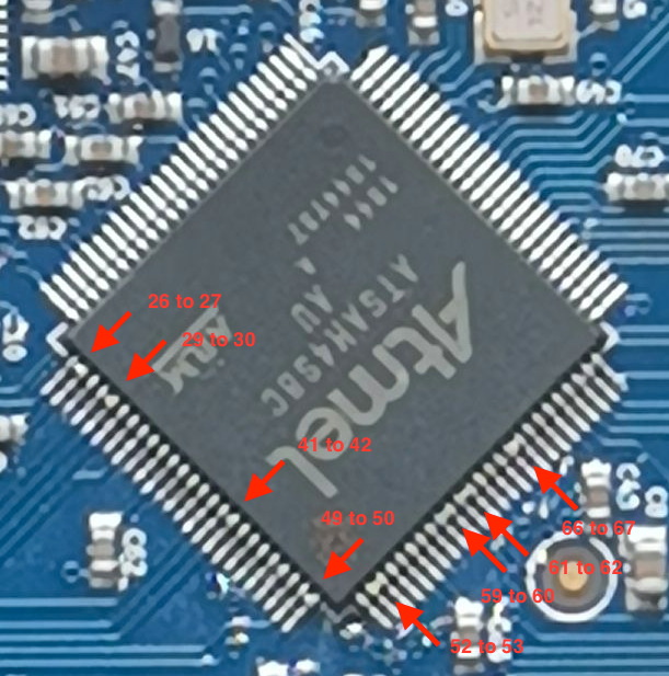
List of possible shorts: 26 to 27, 29 to 30, 41 to 42, 49 to 50, 52 to 53, 59 to 60, 61 to 62, 66 to 67
Most notably, pin 60 is Reset, while pin 59 is one of the SD card pins.It is unusual to see shorts that close to the plastic package though, unless the soldering has been reworked by hand, and it might even be a trick of the light. Please can you check whether those pairs look shorted, and if possible get a sharper photo. We find it best to pull the camera away a bit and use digital zoom. For example, this is from my iPhone SE (I know, but I like a phone that fits in my pocket...):

If you have solder wick, you can try removing the solder bridges. Even wiping a fine-tipped, clean soldering iron on the pins, and pulling in the direction away from the chip, might be enough to remove the solder bridge.
Let me know how you get on, and sorry for the inconvenience.
Ian
Bed-slinger - Mini5+ WiFi/1LC | RRP Fisher v1 - D2 WiFi | Polargraph - D2 WiFi | TronXY X5S - 6HC/Roto | CNC router - 6HC | Tractus3D T1250 - D2 Eth
-
Even wiping a fine-tipped, clean soldering iron on the pins, and pulling in the direction away from the chip, might be enough to remove the solder bridge.
some good flux makes that easier, solder will follow the heat and pull away the bridges
-
Sorry guys. That seem to be only jpg compression or Huawei playing tricks on us. None of those bridges on the cpu. Ill use my dslr to supply with better images. Will do it in the morning..
-
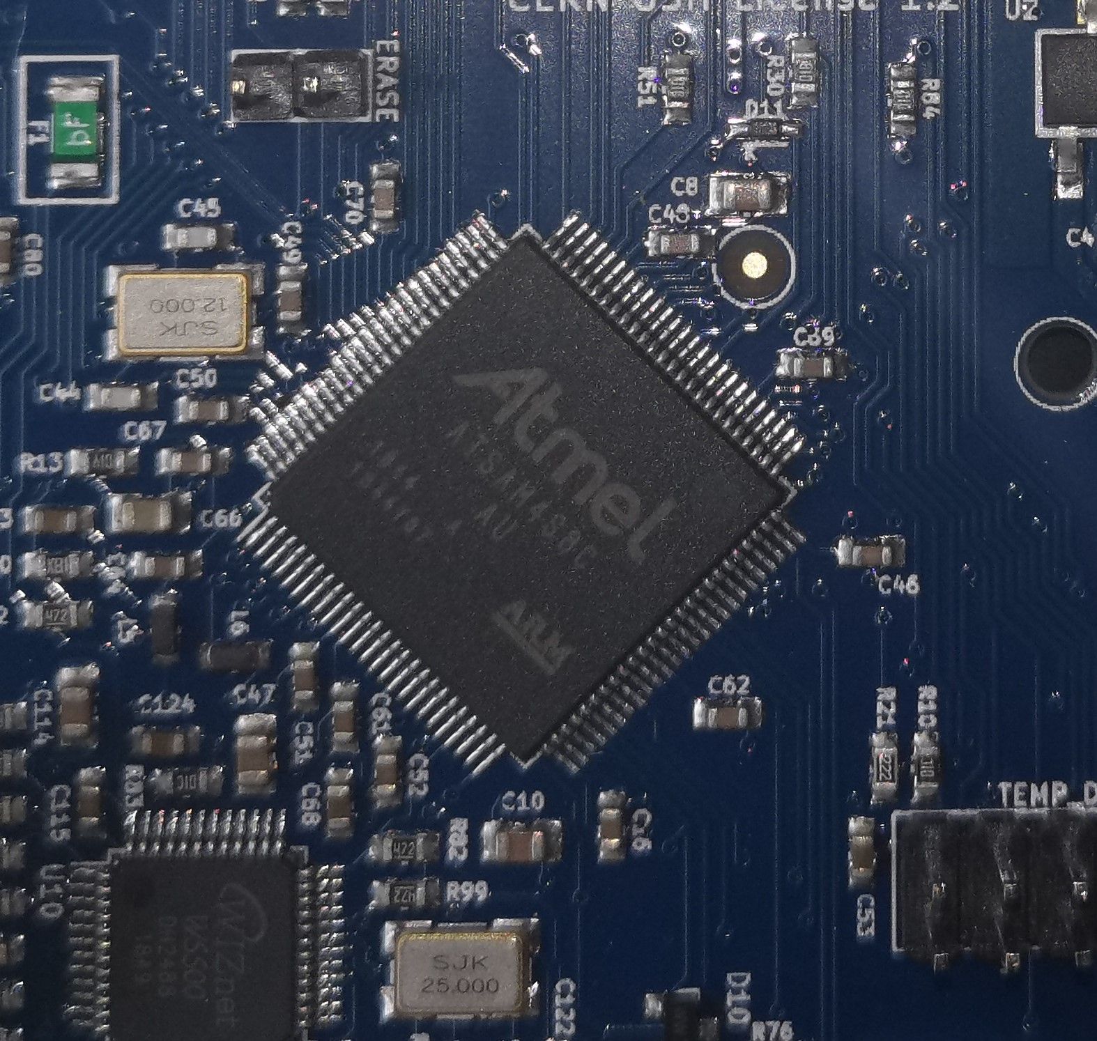
Here is an updated image of the CPU..
-
@massynrt oh that’s disappointing, thought we were on to something! Though with that many bridges, it would be amazing if it worked at all!
I can also see R84 looks okay, too, but please visually check that.
Okay, back to plan A. Do you want to try desoldering the reset switch? Ideally with hot air rework station, or qwikchip, so the chances of lifting pads is minimised.
Ian
-
Sorry for my silly question.. I cant find R84. I looked at the whole pcb and could not find any problems. Even did a good old shock test while it was at operating temp. Does not reset. Almost certain it is not the button or a loose component.
I dont have any fancy tools to remove the.button. Only solder sucker and iron. But this will be last resort only after confirmation of warranty replacement as advised.
I will send you a pm with and alternative solution.
-
@massynrt R84 is in the top right of your DSLR picture of the processor.
I think it’s probably a faulty component that builds capacitance, until something triggers it causing the board to reset. Could also be heat related, as it doesn’t happen when board is idle, only when running. Possibly just a faulty processor with the above issues. Really difficult to say!
Ian
-
Quick question.. the connectors for the motors are upside down vs the meastro. Thus, i have to redo them.. although the red blue green black is still the same.. .
What is the reason? Do i have to redo, or will it still work?
-
Might be something ooznest did with their config. I turning the white clips around.
-
@massynrt said in Duet Maestro 2 stops mid print:
Do i have to redo, or will it still work?
it might run in reverse if you swap 1<->4 and 2<->3 but that can be fixed by reversing the config.
as to reason, unclear; are you refering to duet 3 vs duet 2 maestro? in any case to make routing the board easier is the likely answer.
-
@massynrt all Duets connect the motor phases the same way; one phase/coil to pins 1 and 2 of the motor driver pins, and the other phase/coil to pins 3 and 4. The labels on the wiring diagrams and on the PCBs have varied somewhat, for a number of reasons, but this order is the one that is implied, and is common to all Duets. It shouldn’t matter is you flip the wires per coil, as it will just change the motor direction, which you can change with M569 S[0/1].
So you shouldn’t need to change the motor wiring when changing from Maestro to Duet Ethernet, but you may need to change the direction in config.g.
Ian
-
Thanks for all your help @droftarts. I got the Duet 2 up and running.. Busy with first test print..
2 Observations:
- The prints are definitely slower. With the same config file, Except for the BL Touch config. The rest seems to stay the same from Maestro to Duet 2 .
- The motors are quiter. Alot.. Printer just feels better..
Any idea why??
-
@massynrt number 2 is because it’s different stepper drivers, and quieter because of different StealthChop settings. Not sure why it would be slower, though!
Ian
-
Spidy sense senses board has been replaced?
Does that mean its too late to suggest trying a stronger pull up between a reset pin and 3.3v?