Ender 5 Pro Hemera Bltouch upgrade to Duet Wifi Firmware 3
-
@Phaedrux
This is the home all macro; homeall.g
; called to home all axes
;
; generated by RepRapFirmware Configuration Tool v2.1.8 on Sat Apr 18 2020 19:50:27 GMT-0400 (Eastern Daylight Time)
G91 ; relative positioning
G1 H2 Z5 F6000 ; lift Z relative to current position
G1 H1 X-225 Y-225 F1800 ; move quickly to X and Y axis endstops and stop there (first pass)
G1 H2 X5 Y5 F6000 ; go back a few mm
G1 H1 X-225 Y-225 F360 ; move slowly to X and Y axis endstops once more (second pass)
G90 ; absolute positioning
G1 X60 Y12 F6000 ; go to first bed probe point and home Z
G30 ; home Z by probing the bed; Uncomment the following lines to lift Z after probing
;G91 ; relative positioning
;G1 Z5 F100 ; lift Z relative to current position
;G90 ; absolute positioning -
In my brain, Standing in front of the printer, the 0 x and 0 y is where the end of the run switches are. Meaning, back right corner. When those switches are closed, the lights in the motherboard turn red.
When the printer turns on, the Bl touch goes up and down 2 times and then the light remains red and the prob is retracted. -
M401 and M402 work fine deploying and retracting the probe.
-
@Daniel said in Ender 5 Pro Hemera Bltouch upgrade to Duet Wifi Firmware 3:
In my brain, Standing in front of the printer, the 0 x and 0 y is where the end of the run switches are. Meaning, back right corner.
Ok, this is fine. We'll roll with that mental model. Technically this is a 180 degree rotation of the "normal" way of doing it, but it's all relative.
Your config is currently setup to work this way, but the one thing we need to verify is the direction of the motors so that when you send a negative movement command they move to the right and rear towards the endstops.
So can you do a test for me?
With the printer powered off, manually move the print head to the center in X and Y.
When the printer is freshly powered on, go to the gcode console.
Send these commands:
G92 X100 Y100
G91
G1 X-10
G1 Y-10Does the print head move towards the endstops in both cases?
@Daniel said in Ender 5 Pro Hemera Bltouch upgrade to Duet Wifi Firmware 3:
M401 and M402 work fine deploying and retracting the probe.
That's good. Did you also remove the +zprobe.mod from the M558 command in config.g?
-
@Phaedrux
This is the last config file matching all the other files you see above.
I promise not to touch anything else until you return to me.; Configuration file for Duet WiFi (firmware version 3)
; executed by the firmware on start-up
;
; generated by RepRapFirmware Configuration Tool v2.1.8 on Sat Apr 18 2020 19:50:27 GMT-0400 (Eastern Daylight Time); General preferences
G90 ; send absolute coordinates...
M83 ; ...but relative extruder moves
M550 P"Daniel Ender 5" ; set printer name; Network
M552 S1 ; enable network
M586 P0 S1 ; enable HTTP
M586 P1 S0 ; disable FTP
M586 P2 S0 ; disable Telnet; Drives
M569 P0 S1 ; physical drive 0 goes forwards
M569 P1 S1 ; physical drive 1 goes forwards
M569 P2 S0 ; physical drive 2 goes backwards
M569 P3 S1 ; physical drive 3 goes forwards
M584 X0 Y1 Z2 E3 ; set drive mapping
M350 X16 Y16 Z16 E16 I1 ; configure microstepping with interpolation
M92 X80.00 Y80.00 Z800.00 E409.00 ; set steps per mm
M566 X900.00 Y900.00 Z12.00 E300.00 ; set maximum instantaneous speed changes (mm/min)
M203 X18000.00 Y18000.00 Z600.00 E1200.00 ; set maximum speeds (mm/min)
M201 X500.00 Y500.00 Z50.00 E5000.00 ; set accelerations (mm/s^2)
M906 X800 Y800 Z800 E800 I30 ; set motor currents (mA) and motor idle factor in per cent
M84 S30 ; Set idle timeout; Axis Limits
M208 X0 Y0 Z0 S1 ; set axis minima
M208 X220 Y220 Z300 S0 ; set axis maxima; Endstops
M574 X1 S1 P"xstop" ; configure active-high endstop for low end on X via pin xstop
M574 Y1 S1 P"ystop" ; configure active-high endstop for low end on Y via pin ystop
M574 Z1 S2 ; configure Z-probe endstop for low end on Z; Z-Probe
M950 S0 C"exp.heater3" ; create servo pin 0 for BLTouch
M558 P9 C"zprobe.in" H5 F120 T6000 ; set Z probe type to bltouch and the dive height + speeds
G31 P500 X-45 Y3 Z2.5 ; set Z probe trigger value, offset and trigger height
M557 X15:160 Y15:200 S20 ; define mesh grid; Heaters
M308 S0 P"bedtemp" Y"thermistor" T100000 B4138 ; configure sensor 0 as thermistor on pin bedtemp
M950 H0 C"bedheat" T0 ; create bed heater output on bedheat and map it to sensor 0
M143 H0 S120 ; set temperature limit for heater 0 to 120C
M307 H0 B0 S1.00 ; disable bang-bang mode for the bed heater and set PWM limit
M140 H0 ; map heated bed to heater 0
M308 S1 P"e0temp" Y"thermistor" T100000 B4138 ; configure sensor 1 as thermistor on pin e0temp
M950 H1 C"e0heat" T1 ; create nozzle heater output on e0heat and map it to sensor 1
M143 H1 S280 ; set temperature limit for heater 1 to 280C
M307 H1 B0 S1.00 ; disable bang-bang mode for heater and set PWM limit; Fans
M950 F0 C"fan0" Q500 ; create fan 0 on pin fan0 and set its frequency
M106 P0 S0 H-1 ; set fan 0 value. Thermostatic control is turned off
M950 F1 C"fan1" Q500 ; create fan 1 on pin fan1 and set its frequency
M106 P1 S1 H1 T45 ; set fan 1 value. Thermostatic control is turned on; Tools
M563 P0 D0 H1 F0 ; define tool 0
G10 P0 X0 Y0 Z0 ; set tool 0 axis offsets
G10 P0 R0 S0 ; set initial tool 0 active and standby temperatures to 0C; Custom settings are not defined
-
@Daniel said in Ender 5 Pro Hemera Bltouch upgrade to Duet Wifi Firmware 3:
M92 X80.00 Y80.00 Z800.00 E409.00 ; set steps per mm
Also we should test that your z axis steps per mm is correct at 800. In addition to the test above in the console, send the following making sure that your bed is safely away from your nozzle.
G92 Z0
G91
G1 Z10This should move the bed 10mm down away from the nozzle. If it does anything else, kill the power.
Measure how far it actually moves.
-
@Phaedrux
From me standing in front of the printerG1 X-10 moved right
G1 Y-10 moved back -
Ok, now what happens if you test the endstops as described here: https://duet3d.dozuki.com/Guide/Ender+3+Pro+and+Duet+Maestro+Guide+Part+3:+Commissioning/39#s145
-
The G1 Z10 moved the bed exactly 10.27mm downwards
-
Before I moved anything, with the head in the center of the bed (approx) the endstops look like this
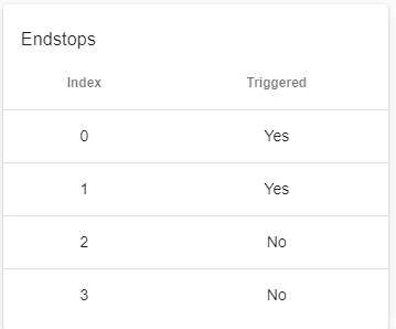
What it is basically wrong. They are opened.
-
@Phaedrux
When I close the circuit by pushing the trigger, both Circuits change to "No"This is really confusing, Triggered means closed or open?
-
@Phaedrux
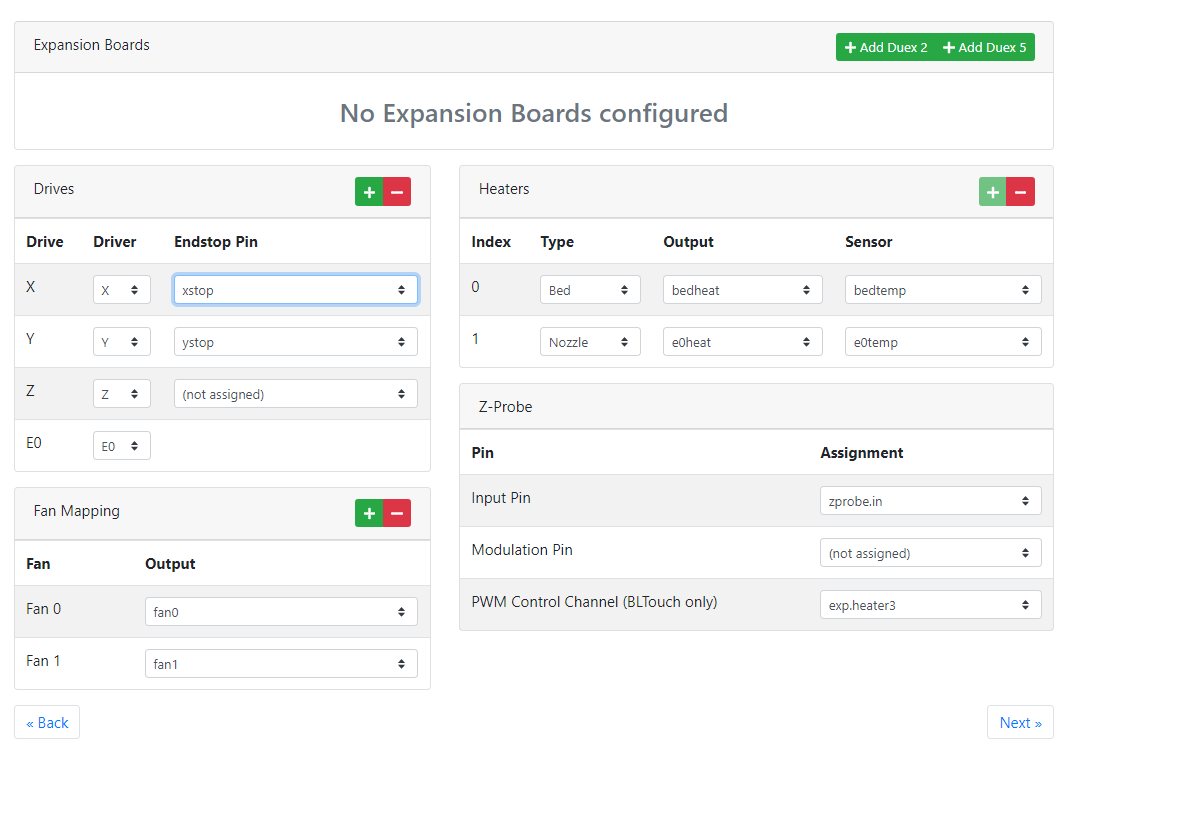
What would be the right switch to choose between all this?
-
xstop,
Xstop inverted
xstop pull up
xstop inverted pull upor should I changed in the next page?
-
You also said my logic was inverted 180 degrees. How should I look at all this (I am left handed and brain washed)

-
I believe we should choose in this last screen, Active low, High end to reverse the screen and finally change the direction of the motors by selecting reverse direction in X and Y.
What say you? I am going to give it a try....
Then - X would be with the motor moving to the left and -Y would be with the motor moving towards the front....and it will match the deviation of the bltouch probe in -x (45 and 3) +y -
Sorry for the delay.
For the endstops we can change them in config.g
M574 X1 S1 P"xstop" ; configure active-high endstop for low end on X via pin xstop M574 Y1 S1 P"ystop" ; configure active-high endstop for low end on Y via pin ystopChange the S1 to S2 for both. Then test the endstops again.
-
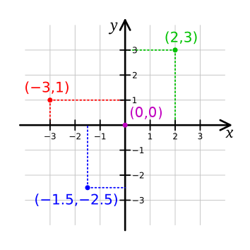
Doing high end for both would give you the 180 degree rotation we discussed earlier.
This is normally how the coordinate system would appear when looking at your printer from the front. The homing location is irrelevant. Instead of homing to 0 it would home to 280 or whatever.
-
@Phaedrux
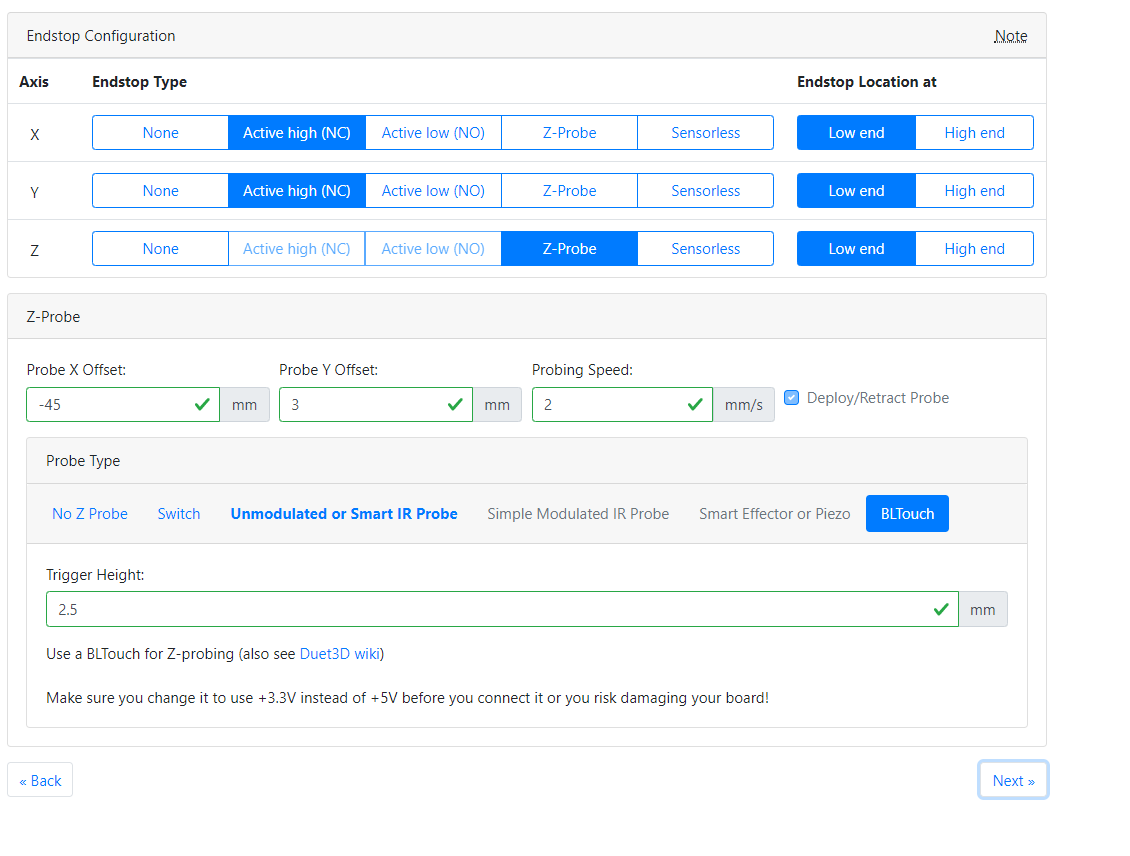
Ok, I tried changing the configuration without success on the RRF to try to get those S2 values to show. I finally changed it on the config and we are like this; Configuration file for Duet WiFi (firmware version 3)
; executed by the firmware on start-up
;
; generated by RepRapFirmware Configuration Tool v2.1.8 on Sat Apr 18 2020 22:46:43 GMT-0400 (Eastern Daylight Time); General preferences
G90 ; send absolute coordinates...
M83 ; ...but relative extruder moves
M550 P"Daniel Ender 5" ; set printer name; Network
M552 S1 ; enable network
M586 P0 S1 ; enable HTTP
M586 P1 S0 ; disable FTP
M586 P2 S0 ; disable Telnet; Drives
M569 P0 S0 ; physical drive 0 goes backwards
M569 P1 S0 ; physical drive 1 goes backwards
M569 P2 S0 ; physical drive 2 goes backwards
M569 P3 S1 ; physical drive 3 goes forwards
M584 X0 Y1 Z2 E3 ; set drive mapping
M350 X16 Y16 Z16 E16 I1 ; configure microstepping with interpolation
M92 X80.00 Y80.00 Z779.00 E409.00 ; set steps per mm
M566 X900.00 Y900.00 Z12.00 E300.00 ; set maximum instantaneous speed changes (mm/min)
M203 X18000.00 Y18000.00 Z900.00 E1200.00 ; set maximum speeds (mm/min)
M201 X500.00 Y500.00 Z50.00 E5000.00 ; set accelerations (mm/s^2)
M906 X800 Y800 Z800 E800 I30 ; set motor currents (mA) and motor idle factor in per cent
M84 S30 ; Set idle timeout; Axis Limits
M208 X0 Y0 Z0 S1 ; set axis minima
M208 X220 Y220 Z300 S0 ; set axis maxima; Endstops
M574 X2 S2 P"xstop" ; configure active-high endstop for high end on X via pin xstop
M574 Y2 S2 P"ystop" ; configure active-high endstop for high end on Y via pin ystop
M574 Z1 S2 ; configure Z-probe endstop for low end on Z; Z-Probe
M950 S0 C"exp.heater3" ; create servo pin 0 for BLTouch
M558 P9 C"zprobe.in" H5 F120 T6000 ; set Z probe type to bltouch and the dive height + speeds
G31 P500 X-45 Y3 Z2.5 ; set Z probe trigger value, offset and trigger height
M557 X15:160 Y15:200 S20 ; define mesh grid; Heaters
M308 S0 P"bedtemp" Y"thermistor" T100000 B4138 ; configure sensor 0 as thermistor on pin bedtemp
M950 H0 C"bedheat" T0 ; create bed heater output on bedheat and map it to sensor 0
M143 H0 S120 ; set temperature limit for heater 0 to 120C
M307 H0 B0 S1.00 ; disable bang-bang mode for the bed heater and set PWM limit
M140 H0 ; map heated bed to heater 0
M308 S1 P"e0temp" Y"thermistor" T100000 B4138 ; configure sensor 1 as thermistor on pin e0temp
M950 H1 C"e0heat" T1 ; create nozzle heater output on e0heat and map it to sensor 1
M143 H1 S300 ; set temperature limit for heater 1 to 300C
M307 H1 B0 S1.00 ; disable bang-bang mode for heater and set PWM limit; Fans
M950 F0 C"fan0" Q500 ; create fan 0 on pin fan0 and set its frequency
M106 P0 S0 H-1 ; set fan 0 value. Thermostatic control is turned off
M950 F1 C"fan1" Q500 ; create fan 1 on pin fan1 and set its frequency
M106 P1 S1 H1 T45 ; set fan 1 value. Thermostatic control is turned on; Tools
M563 P0 S"E3D V6 Nozzle X" D0 H1 F0 ; define tool 0
G10 P0 X0 Y0 Z0 ; set tool 0 axis offsets
G10 P0 R0 S0 ; set initial tool 0 active and standby temperatures to 0C; Custom settings are not defined
-
However in our machine specific configuration, the end stops continue to show like this when the head is in the middle of the bed....
Is this right?
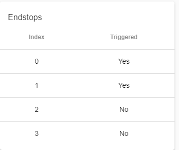
-
@Daniel said in Ender 5 Pro Hemera Bltouch upgrade to Duet Wifi Firmware 3:
M574 X2 S2 P"xstop" ; configure active-high endstop for high end on X via pin xstop
M574 Y2 S2 P"ystop" ; configure active-high endstop for high end on Y via pin ystopDid you get a full new config set from the configurator? At this point it may be easier (for me anyway) if you stick with one config and we manually alter it. If you keep changing things in the configurator it makes it a lot harder to notice everything that's changed.
For instance the config now has Y2 X2, which would be the high end of travel. That's fine, it would be the more traditional way of doing it.
@Daniel said in Ender 5 Pro Hemera Bltouch upgrade to Duet Wifi Firmware 3:
However in our machine specific configuration, the end stops continue to show like this when the head is in the middle of the bed....
Is this right?

Can you post a photo of the endstops and how you have them wired?
