Duet3D Logo Duet3D
    • Tags
    • Documentation
    • Order
    • Register
    • Login

    Ender 5 Pro Hemera Bltouch upgrade to Duet Wifi Firmware 3

    Scheduled Pinned Locked Moved
    Tuning and tweaking
    4
    43
    2.1k
    Loading More Posts
    • Oldest to Newest
    • Newest to Oldest
    • Most Votes
    Reply
    • Reply as topic
    Log in to reply
    This topic has been deleted. Only users with topic management privileges can see it.
    • Phaedruxundefined
      Phaedrux Moderator
      last edited by

      Ok, now what happens if you test the endstops as described here: https://duet3d.dozuki.com/Guide/Ender+3+Pro+and+Duet+Maestro+Guide+Part+3:+Commissioning/39#s145

      Z-Bot CoreXY Build | Thingiverse Profile

      1 Reply Last reply Reply Quote 0
      • Danielundefined
        Daniel
        last edited by

        @Phaedrux

        The G1 Z10 moved the bed exactly 10.27mm downwards

        1 Reply Last reply Reply Quote 0
        • Danielundefined
          Daniel
          last edited by

          Before I moved anything, with the head in the center of the bed (approx) the endstops look like this
          402528a9-ac2d-48c9-ba5c-dc459b372105-image.png

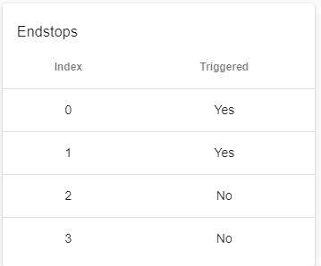
          What it is basically wrong. They are opened.

          1 Reply Last reply Reply Quote 0
          • Danielundefined
            Daniel
            last edited by

            @Phaedrux
            When I close the circuit by pushing the trigger, both Circuits change to "No"

            This is really confusing, Triggered means closed or open?

            1 Reply Last reply Reply Quote 0
            • Danielundefined
              Daniel
              last edited by

              @Phaedrux
              What would be the right switch to choose between all this?
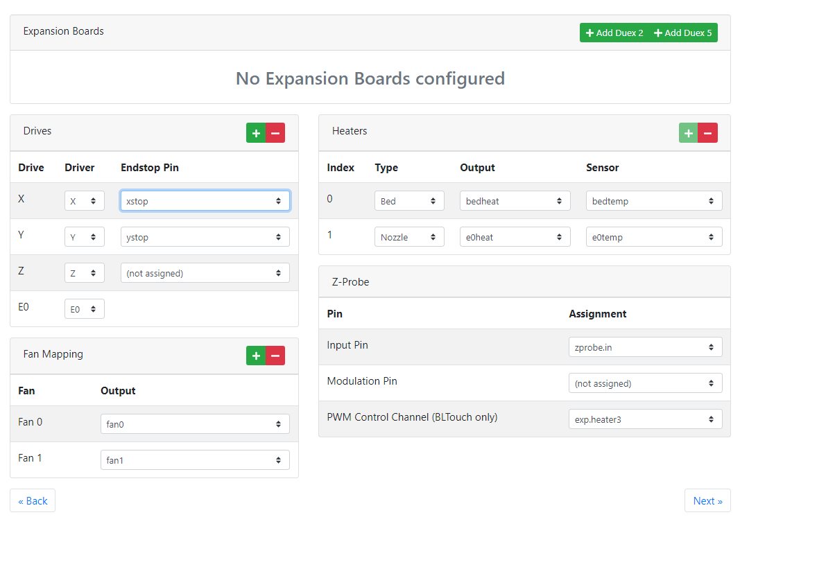
              0ee16afa-a0e4-410b-906f-ae9dd57b1829-image.png

              1 Reply Last reply Reply Quote 0
              • Danielundefined
                Daniel
                last edited by

                @Phaedrux

                xstop,
                Xstop inverted
                xstop pull up
                xstop inverted pull up

                or should I changed in the next page?

                1 Reply Last reply Reply Quote 0
                • Danielundefined
                  Daniel
                  last edited by

                  @Phaedrux
                  4885e28b-3ff6-493e-b5d7-7cdc778b2872-image.png

                  You also said my logic was inverted 180 degrees. How should I look at all this (I am left handed and brain washed) 😉

                  1 Reply Last reply Reply Quote 0
                  • Danielundefined
                    Daniel
                    last edited by

                    @Phaedrux

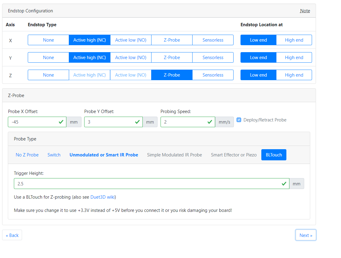
                    I believe we should choose in this last screen, Active low, High end to reverse the screen and finally change the direction of the motors by selecting reverse direction in X and Y.

                    What say you? I am going to give it a try....
                    Then - X would be with the motor moving to the left and -Y would be with the motor moving towards the front....and it will match the deviation of the bltouch probe in -x (45 and 3) +y

                    1 Reply Last reply Reply Quote 0
                    • Phaedruxundefined
                      Phaedrux Moderator
                      last edited by

                      Sorry for the delay.

                      For the endstops we can change them in config.g

                      M574 X1 S1 P"xstop" ; configure active-high endstop for low end on X via pin xstop
                      M574 Y1 S1 P"ystop" ; configure active-high endstop for low end on Y via pin ystop
                      

                      Change the S1 to S2 for both. Then test the endstops again.

                      Z-Bot CoreXY Build | Thingiverse Profile

                      1 Reply Last reply Reply Quote 0
                      • Phaedruxundefined
                        Phaedrux Moderator
                        last edited by

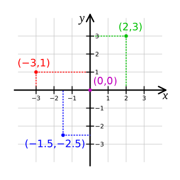
                        Doing high end for both would give you the 180 degree rotation we discussed earlier.

                        This is normally how the coordinate system would appear when looking at your printer from the front. The homing location is irrelevant. Instead of homing to 0 it would home to 280 or whatever.

                        Cartesian-coordinate-system.png

                        Z-Bot CoreXY Build | Thingiverse Profile

                        Danielundefined 1 Reply Last reply Reply Quote 0
                        • Danielundefined
                          Daniel @Phaedrux
                          last edited by

                          @Phaedrux
                          Ok, I tried changing the configuration without success on the RRF to try to get those S2 values to show. I finally changed it on the config and we are like this

                          ; Configuration file for Duet WiFi (firmware version 3)
                          ; executed by the firmware on start-up
                          ;
                          ; generated by RepRapFirmware Configuration Tool v2.1.8 on Sat Apr 18 2020 22:46:43 GMT-0400 (Eastern Daylight Time)

                          ; General preferences
                          G90 ; send absolute coordinates...
                          M83 ; ...but relative extruder moves
                          M550 P"Daniel Ender 5" ; set printer name

                          ; Network
                          M552 S1 ; enable network
                          M586 P0 S1 ; enable HTTP
                          M586 P1 S0 ; disable FTP
                          M586 P2 S0 ; disable Telnet

                          ; Drives
                          M569 P0 S0 ; physical drive 0 goes backwards
                          M569 P1 S0 ; physical drive 1 goes backwards
                          M569 P2 S0 ; physical drive 2 goes backwards
                          M569 P3 S1 ; physical drive 3 goes forwards
                          M584 X0 Y1 Z2 E3 ; set drive mapping
                          M350 X16 Y16 Z16 E16 I1 ; configure microstepping with interpolation
                          M92 X80.00 Y80.00 Z779.00 E409.00 ; set steps per mm
                          M566 X900.00 Y900.00 Z12.00 E300.00 ; set maximum instantaneous speed changes (mm/min)
                          M203 X18000.00 Y18000.00 Z900.00 E1200.00 ; set maximum speeds (mm/min)
                          M201 X500.00 Y500.00 Z50.00 E5000.00 ; set accelerations (mm/s^2)
                          M906 X800 Y800 Z800 E800 I30 ; set motor currents (mA) and motor idle factor in per cent
                          M84 S30 ; Set idle timeout

                          ; Axis Limits
                          M208 X0 Y0 Z0 S1 ; set axis minima
                          M208 X220 Y220 Z300 S0 ; set axis maxima

                          ; Endstops
                          M574 X2 S2 P"xstop" ; configure active-high endstop for high end on X via pin xstop
                          M574 Y2 S2 P"ystop" ; configure active-high endstop for high end on Y via pin ystop
                          M574 Z1 S2 ; configure Z-probe endstop for low end on Z

                          ; Z-Probe
                          M950 S0 C"exp.heater3" ; create servo pin 0 for BLTouch
                          M558 P9 C"zprobe.in" H5 F120 T6000 ; set Z probe type to bltouch and the dive height + speeds
                          G31 P500 X-45 Y3 Z2.5 ; set Z probe trigger value, offset and trigger height
                          M557 X15:160 Y15:200 S20 ; define mesh grid

                          ; Heaters
                          M308 S0 P"bedtemp" Y"thermistor" T100000 B4138 ; configure sensor 0 as thermistor on pin bedtemp
                          M950 H0 C"bedheat" T0 ; create bed heater output on bedheat and map it to sensor 0
                          M143 H0 S120 ; set temperature limit for heater 0 to 120C
                          M307 H0 B0 S1.00 ; disable bang-bang mode for the bed heater and set PWM limit
                          M140 H0 ; map heated bed to heater 0
                          M308 S1 P"e0temp" Y"thermistor" T100000 B4138 ; configure sensor 1 as thermistor on pin e0temp
                          M950 H1 C"e0heat" T1 ; create nozzle heater output on e0heat and map it to sensor 1
                          M143 H1 S300 ; set temperature limit for heater 1 to 300C
                          M307 H1 B0 S1.00 ; disable bang-bang mode for heater and set PWM limit

                          ; Fans
                          M950 F0 C"fan0" Q500 ; create fan 0 on pin fan0 and set its frequency
                          M106 P0 S0 H-1 ; set fan 0 value. Thermostatic control is turned off
                          M950 F1 C"fan1" Q500 ; create fan 1 on pin fan1 and set its frequency
                          M106 P1 S1 H1 T45 ; set fan 1 value. Thermostatic control is turned on

                          ; Tools
                          M563 P0 S"E3D V6 Nozzle X" D0 H1 F0 ; define tool 0
                          G10 P0 X0 Y0 Z0 ; set tool 0 axis offsets
                          G10 P0 R0 S0 ; set initial tool 0 active and standby temperatures to 0C

                          ; Custom settings are not defined

                          Phaedruxundefined 1 Reply Last reply Reply Quote 0
                          • Danielundefined
                            Daniel
                            last edited by

                            @Phaedrux

                            However in our machine specific configuration, the end stops continue to show like this when the head is in the middle of the bed....

                            Is this right?

                            c8e4bc4f-7f9e-41ca-a438-73ebcddf7464-image.png

                            1 Reply Last reply Reply Quote 0
                            • Phaedruxundefined
                              Phaedrux Moderator @Daniel
                              last edited by

                              @Daniel said in Ender 5 Pro Hemera Bltouch upgrade to Duet Wifi Firmware 3:

                              M574 X2 S2 P"xstop" ; configure active-high endstop for high end on X via pin xstop
                              M574 Y2 S2 P"ystop" ; configure active-high endstop for high end on Y via pin ystop

                              Did you get a full new config set from the configurator? At this point it may be easier (for me anyway) if you stick with one config and we manually alter it. If you keep changing things in the configurator it makes it a lot harder to notice everything that's changed.

                              For instance the config now has Y2 X2, which would be the high end of travel. That's fine, it would be the more traditional way of doing it.

                              @Daniel said in Ender 5 Pro Hemera Bltouch upgrade to Duet Wifi Firmware 3:

                              @Phaedrux

                              However in our machine specific configuration, the end stops continue to show like this when the head is in the middle of the bed....

                              Is this right?

                              c8e4bc4f-7f9e-41ca-a438-73ebcddf7464-image.png

                              Can you post a photo of the endstops and how you have them wired?

                              Z-Bot CoreXY Build | Thingiverse Profile

                              1 Reply Last reply Reply Quote 0
                              • Danielundefined
                                Daniel
                                last edited by

                                @Phaedrux
                                Sorry Phaedrux,
                                I was trying to get this to show more like your logic, so the alignment on the Bltouch later comes easier to you.
                                Let me take the pictures and return to you.

                                1 Reply Last reply Reply Quote 0
                                • Danielundefined
                                  Daniel
                                  last edited by

                                  @Phaedrux

                                  Here are the pictures of the motherboard and the Y endswitch

                                  IMG_1551.jpg IMG_1552.jpg

                                  1 Reply Last reply Reply Quote 0
                                  • Danielundefined
                                    Daniel
                                    last edited by

                                    @Phaedrux

                                    I have oriented the colors to match the letters for Signal Ground and Voltage in the printer run end sensor and in the motherboard. Double Checked.
                                    The original wire on the Ender 5 is a 2 wire cable. Just connected in both ends of the run end sensor = S and V
                                    The instructions on the Duet 2 page mention the 2 wires from the ender connector should be connected on the outer two of the three connectors on the motherboard (leave the center empty). That would mean that S and V from the ender should be connected to S and G in the motherboard.
                                    That did not seem right to me, so I preferred to keep the convention matched on both circuits and made my own cable.

                                    Phaedrux, Whatever they pay you to do this job (if any) is too little.... please let me know how can I compensate all this help and assistance. Best regards. Daniel

                                    jumpedwithbothfeetundefined 1 Reply Last reply Reply Quote 0
                                    • Phaedruxundefined
                                      Phaedrux Moderator
                                      last edited by Phaedrux

                                      Ok, those 3 wire endstops might need to be wired a little differently, I'm not sure because I'm having a hard time orienting your photo against the wiring diagram.

                                      But hopefully based on this info and the wiring diagram you can verify it.

                                      https://duet3d.dozuki.com/Wiki/Connecting_endstop_switches#Section_Makerbot_Mechanical_Endstop_v1_Num_2

                                      https://duet3d.dozuki.com/Wiki/Connecting_endstop_switches#Section_Microswitch

                                      https://duet3d.dozuki.com/Wiki/Duet_Wiring_Diagrams

                                      Z-Bot CoreXY Build | Thingiverse Profile

                                      1 Reply Last reply Reply Quote 0
                                      • Phaedruxundefined
                                        Phaedrux Moderator
                                        last edited by

                                        Nope, sorry, disregard that. You only need the 2 wires for that endstop connected to the outer two pins on the endstop port. Doesn't matter which way.

                                        https://duet3d.dozuki.com/Guide/Ender+3+Pro+and+Duet+Maestro+Guide+Part+1:+Wiring/37#s119

                                        Z-Bot CoreXY Build | Thingiverse Profile

                                        1 Reply Last reply Reply Quote 0
                                        • bricorundefined
                                          bricor
                                          last edited by bricor

                                          I found this in the endstop documentation not sure if it applies.

                                          If using RepRapFirmware 3, invert the polarity by putting a ! character in front of the pin name.

                                          1 Reply Last reply Reply Quote 0
                                          • jumpedwithbothfeetundefined
                                            jumpedwithbothfeet @Daniel
                                            last edited by

                                            @Daniel don’t wish to muddy the water as I don’t have a great deal of knowledge, however I also have an ender 5 but running a duet 3, both my end-stops configured using 2 wires only as the they are only normally closed micro switches, I’d hazard a guess your issue is the center wire that’s been added for 3.3v it maybe holding the switch closed, I’ve added my config hopefully it will help 🙂
                                            config.g

                                            Regards Jim

                                            6HC Voron Trident based, 6XD CNC, Mini 5 polar printer

                                            1 Reply Last reply Reply Quote 0
                                            • First post
                                              Last post
                                            Unless otherwise noted, all forum content is licensed under CC-BY-SA