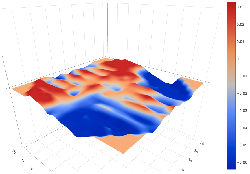
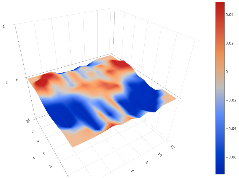
Weird Bed Mesh - Delta - Rostock 3.2
-
@Baenwort Looks much better! There's still the shape there was before, but much subtler, so maybe it's just tweaking the arm length and delta radius now. I think there's also some effector tilt going on, or backlash in one of the axes, as you're getting alternate up/down lines in the X axis direction:
Have you tried running a 7-factor bed calibration? This will tune the arm lengths too.
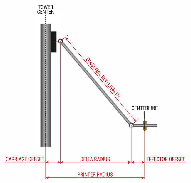
It's very difficult to measure delta radius, and you need to measure the effector radius too:
As you're so close, I'd just let the calibration sort it out.
Ian
Bed-slinger - Mini5+ WiFi/1LC | RRP Fisher v1 - D2 WiFi | Polargraph - D2 WiFi | TronXY X5S - 6HC/Roto | CNC router - 6HC | Tractus3D T1250 - D2 Eth
-
@droftarts I see that given what I have available to measure with it will be difficult as I'm not sure how precisely I would be able to measure from center to center of a open circle. The Effector wouldn't be as hard as I'd have the nozzle to align with and the extruded towers have a center channel I could also use.
Do you suggest tweaking by .5mm or even .1 in a given direction? I don't think the delta radius is the problem but rather the arm length. I've put in a issue on SeeMeCNC's github about this: https://github.com/seemecnc/RostockMaxV3.2/issues/2
I wasn't sure if I could do a S7 calibration as the wiki advice is that you need to be significantly outside the triangle of the towers and I don't think my surface is big enough?


The idea of the carbon arms and milled ball joints was to reduce backlash. I wish I had some more precision to measure tilt as the bubble levels and analog angle gauge I have don't show any issue. Would you suggest anything other then using a bubble level on the effector?


Is there a video host that would be best for me to post a G29 run or other movement video while the bubble ridges the effector?
-
@Baenwort said in Weird Bed Mesh - Delta - Rostock 3.2:
Is there a video host that would be best for me to post a G29 run
Dropbox, vimeo, youtube, google drive
-
@Baenwort In the end, the effector tilt is tiny, I'd say about 0.025mm. It may just be belt tension (equally tension all three belts), or a slight movement/sticking in an X-carriage, or stiction (static friction, ie that some force is needed to move them) in the ball joints. Did you lubricate the ball joints as recommended?
The bigger issue (and again, it's still pretty small, as your max deviation is +/- 0.125mm) is the delta radius and rod length, but I think these are close, and you're not going to get closer by physically measuring it.
I'd say yes, your bed is big enough to use S7 (or S8 or S9, though the bed looks pretty flat). I'd see what they report; you don't have to implement them. Just run them (adjust bed.g so the nozzle probes as close to the edge of the bed as possible, without hitting the towers) and run a bed mesh afterwards, to see if there's an improvement.
Ian
Bed-slinger - Mini5+ WiFi/1LC | RRP Fisher v1 - D2 WiFi | Polargraph - D2 WiFi | TronXY X5S - 6HC/Roto | CNC router - 6HC | Tractus3D T1250 - D2 Eth
-
@droftarts Thanks, I will try driving the nozzle over to the edge of the bed and measuring the coordinates to put into a extra points. I currently have the following bed.g
M203 Z15000
G28

M109 S0
M140 S0
M106 P0 S0
M106 P2 S0 H-1

G30 P0 X0 Y134.9 H0 Z-99999
G30 P1 X67.45 Y116.83 H0 Z-99999
G30 P2 X116.83 Y67.45 H0 Z-99999
G30 P3 X134.9 Y0 H0 Z-99999
G30 P4 X116.83 Y-67.45 H0 Z-99999
G30 P5 X67.45 Y-116.83 H0 Z-99999
G30 P6 X0 Y-134.9 H0 Z-99999
G30 P7 X-67.45 Y-116.83 H0 Z-99999
G30 P8 X-116.83 Y-67.45 H0 Z-99999
G30 P9 X-134.9 Y0 H0 Z-99999
G30 P10 X-116.83 Y67.45 H0 Z-99999
G30 P11 X-67.45 Y116.83 H0 Z-99999
G30 P12 X0 Y67.4 H0 Z-99999
G30 P13 X58.37 Y33.7 H0 Z-99999
G30 P14 X58.37 Y-33.7 H0 Z-99999
G30 P15 X0 Y-67.4 H0 Z-99999
G30 P16 X-58.37 Y-33.7 H0 Z-99999
G30 P17 X-58.37 Y33.7 H0 Z-99999
G30 P18 X0 Y0 H0 Z-99999 S6

M106 P2 T50 S0.5 H1

G28
How many points would you recommend? I am currently going to add 6 more points to the 18 I currently have. Three, each at the base of each tower, as close as I can maneuver the effector; and three, each directly opposite a tower, as far as I can position the nozzle out and still have solid bed under it.
Would that be sufficient for a S7?
I have lubed and cleaned and lubed again the ball joints on both the trucks and the effector ends with the white lube that SeeMeCNC gave with the ball joints. I've noticed that the lube likes to pick up dust and I never found a good recommendation on how much so I think I'm over lubricating out of caution.
-
So I made up some extra bed.g points, that after I modded my config.g to have a B150 in my definition area to let me get closer to the edge, gave me the following bed.g that did not crash anything and reached where I had hoped.
M203 Z15000
G28

M109 S0
M140 S0
M106 P0 S0
M106 P2 S0 H-1

G30 P0 X0 Y134.9 H0 Z-99999
G30 P1 X67.45 Y116.83 H0 Z-99999
G30 P2 X116.83 Y67.45 H0 Z-99999
G30 P3 X134.9 Y0 H0 Z-99999
G30 P4 X116.83 Y-67.45 H0 Z-99999
G30 P5 X67.45 Y-116.83 H0 Z-99999
G30 P6 X0 Y-134.9 H0 Z-99999
G30 P7 X-67.45 Y-116.83 H0 Z-99999
G30 P8 X-116.83 Y-67.45 H0 Z-99999
G30 P9 X-134.9 Y0 H0 Z-99999
G30 P10 X-116.83 Y67.45 H0 Z-99999
G30 P11 X-67.45 Y116.83 H0 Z-99999
G30 P12 X0 Y67.4 H0 Z-99999
G30 P13 X58.37 Y33.7 H0 Z-99999
G30 P14 X58.37 Y-33.7 H0 Z-99999
G30 P15 X0 Y-67.4 H0 Z-99999
G30 P16 X-58.37 Y-33.7 H0 Z-99999
G30 P17 X-58.37 Y33.7 H0 Z-99999
G30 P18 X-120 Y-70 H0 Z-99999 ;Xtower Base
G30 P19 X120 Y-70 H0 Z-99999 ;Ytower Base
G30 P20 X0 Y145 H0 Z-99999 ;Ztower Base
G30 P21 X132 Y70 H0 Z-99999 ;Xtower Cross
G30 P22 X-130 Y75 H0 Z-99999 ;Ytower Cross
G30 P23 X0 Y-150 H0 Z-99999 ;Ztower Cross
G30 P24 X0 Y0 H0 Z-99999 S9

M106 P2 T50 S0.5 H1

G28
This resulted in the following new config-overridge.g after three G32 runs followed by a M500.
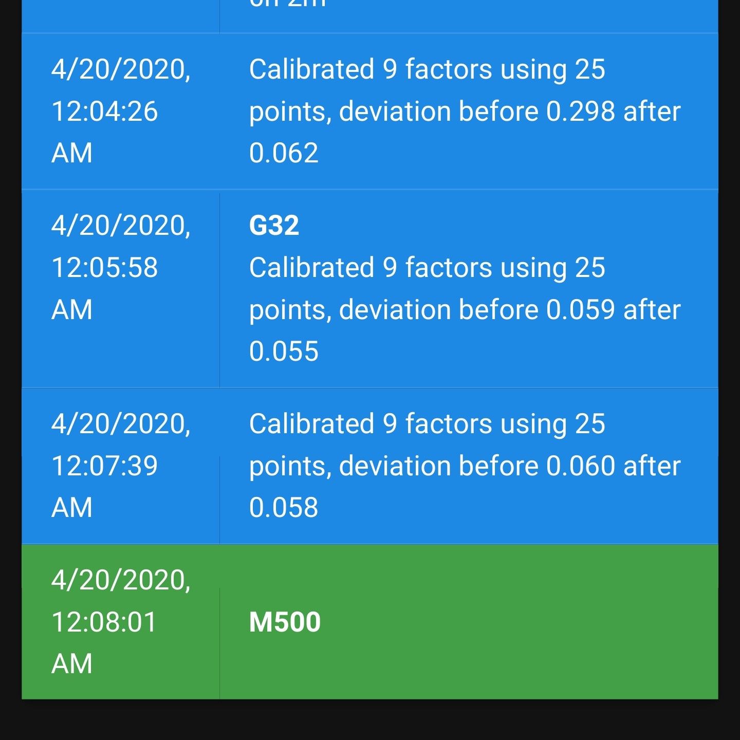
; config-override.g file generated in response to M500 at 2020-04-19 23:33
; This is a system-generated file - do not edit
; Delta parameters
M665 L342.562:342.562:342.562 R142.418 H342.097 B150.0 X-0.284 Y-0.224 Z0.000
M666 X-0.634 Y-0.553 Z1.187 A0.01 B0.25
; Heater model parameters
M307 H0 A90.0 C700.0 D10.0 S1.00 V0.0 B0
M307 H1 A340.0 C140.0 D5.5 S1.00 V0.0 B0
M307 H2 A340.0 C140.0 D5.5 S1.00 V0.0 B0
M307 H3 A340.0 C140.0 D5.5 S1.00 V0.0 B0
M307 H4 A340.0 C140.0 D5.5 S1.00 V0.0 B0
M307 H5 A340.0 C140.0 D5.5 S1.00 V0.0 B0
M307 H6 A340.0 C140.0 D5.5 S1.00 V0.0 B0
M307 H7 A340.0 C140.0 D5.5 S1.00 V0.0 B0
G10 L2 P1 X0.00 Y0.00 Z0.00
G10 L2 P2 X0.00 Y0.00 Z0.00
G10 L2 P3 X0.00 Y0.00 Z0.00
G10 L2 P4 X0.00 Y0.00 Z0.00
G10 L2 P5 X0.00 Y0.00 Z0.00
G10 L2 P6 X0.00 Y0.00 Z0.00
G10 L2 P7 X0.00 Y0.00 Z0.00
G10 L2 P8 X0.00 Y0.00 Z0.00
G10 L2 P9 X0.00 Y0.00 Z0.00
I then ran a G29 and got this heightmap.csv
RepRapFirmware height map file v2 generated at 2020-04-19 23:42, min error -0.179, max error 0.085, mean -0.021, deviation 0.052 xmin,xmax,ymin,ymax,radius,xspacing,yspacing,xnum,ynum -120.00,120.10,-120.00,120.10,135.00,15.00,15.00,17,17 0, 0, 0, 0, 0.059, 0.030, 0.012, -0.058, -0.032, -0.072, -0.085, -0.136, -0.076, 0, 0, 0, 0 0, 0, 0, 0.085, 0.038, 0.061, 0.042, -0.032, -0.042, -0.085, -0.078, -0.083, -0.134, -0.082, 0, 0, 0 0, 0, 0.043, 0.015, 0.021, 0.020, -0.001, -0.013, -0.033, -0.087, -0.053, -0.063, -0.063, -0.046, -0.089, 0, 0 0, 0.068, 0.036, 0.052, 0.047, 0.039, 0.024, 0.003, -0.042, -0.059, -0.074, -0.107, -0.098, -0.131, -0.109, -0.071, 0 0.014, -0.034, -0.022, -0.030, -0.017, 0.011, -0.058, 0.006, -0.040, -0.044, -0.014, -0.011, -0.027, -0.026, -0.030, -0.036, -0.064 -0.005, -0.014, 0.020, 0.027, 0.015, 0.017, -0.014, 0.015, -0.044, -0.055, -0.051, -0.047, -0.047, -0.058, -0.073, -0.069, -0.041 -0.060, -0.075, -0.029, -0.014, -0.032, -0.021, 0.011, 0.037, -0.018, 0.004, -0.010, -0.011, 0.014, 0.021, 0.026, -0.006, 0.007 -0.021, 0.005, 0.028, 0.042, 0.021, 0.003, 0.006, 0.027, -0.014, -0.002, 0.003, -0.023, -0.023, -0.011, -0.044, -0.046, -0.021 -0.069, -0.036, -0.028, 0.003, -0.013, 0.001, 0.007, -0.025, -0.016, -0.037, 0.005, 0.008, 0.022, 0.048, 0.013, -0.010, 0.033 -0.020, 0.002, 0.040, 0.050, 0.027, 0.018, 0.038, 0.008, -0.017, -0.002, 0.009, 0.005, -0.013, -0.022, -0.053, -0.060, -0.017 -0.039, -0.039, -0.021, -0.024, -0.013, -0.014, 0.025, 0.009, 0.022, 0.003, 0.027, 0.019, 0.037, -0.007, -0.018, -0.023, -0.017 -0.046, -0.007, -0.005, 0.012, 0.032, 0.033, 0.036, 0.051, 0.002, 0.025, -0.038, -0.050, -0.071, -0.054, -0.092, -0.072, -0.051 -0.033, -0.036, -0.022, -0.010, -0.008, 0.002, 0.034, 0.038, 0.049, 0.024, -0.024, -0.057, -0.051, -0.092, -0.085, -0.081, -0.055 0, -0.014, 0.025, 0.041, 0.051, 0.041, 0.046, 0.024, 0.005, -0.027, -0.049, -0.096, -0.123, -0.098, -0.133, -0.085, 0 0, 0, 0.032, 0.038, 0.061, 0.048, 0.035, 0.009, -0.034, -0.060, -0.099, -0.114, -0.106, -0.122, -0.132, 0, 0 0, 0, 0, 0.080, 0.075, 0.071, 0.050, -0.002, -0.051, -0.079, -0.129, -0.149, -0.179, -0.158, 0, 0, 0 0, 0, 0, 0, 0.064, 0.049, 0.030, 0.020, -0.036, -0.089, -0.126, -0.164, -0.158, 0, 0, 0, 0 -
Have you verified the tower steps/mm? An error in the steps/mm setting has a similar effect to an error in the rod length, because it's the product of the two that needs to be right to get a flat print plane, assuming that the delta radius is adjusted to suit. Calibration with S7 gave you an increase in rod length from 340.5 to 342.5 which is abou 0.6%. If your real steps/mm is 0.6% smaller than the value you have used in config.g, that would have a similar effect.
Adjusting rod length or steps/mm will affect the scaling and geometry of printing. I suggest you print a maximum-size square, then check it for correct size and straight edges. Also print a large nought-and-crosses/tic-tac-toe pattern and check that the lines are parallel and correctly spaced.
Duet WiFi hardware designer and firmware engineer
Please do not ask me for Duet support via PM or email, use the forum
http://www.escher3d.com, https://miscsolutions.wordpress.com -
-
@dc42 I have 1.8 degree steppers with 20T pulleys from SeeMeCNC. Per their github and wiki this means I should be using 80 steps/mm for the axis and 91 steps/mm for the EZR Struders. This is what is in my config.g and I'm not sure if you are suggesting I should take 94% percent of 80 and use that?
I can switch out to. 9 steppers and 16T pulleys as I do have them on hand but I wanted to do this upgrade one component at a time.
-
I printed a large circle with crossing lines (the SeeMeCNC test wheel found at https://www.thingiverse.com/thing:3002657 or see my picture) and it measured well.
I am currently looking for a good large square that is the right size to fill the bed. How close to a full bed do I need? The bed is a 310mm circle but I don't plan to print larger than 280mm.
![20200425_230046[1].jpg](/assets/uploads/files/1587873860174-20200425_230046-1-resized.jpg)
![20200425_230228[1].jpg](/assets/uploads/files/1587873910145-20200425_230228-1-resized.jpg)
-
Did a 150mm square as that is the largest accurate measurement device I have.
Printed in ABS.

I don't understand what you mean by a toe print. Can you provide a reference I can scale in Cura?