Weird Bed Mesh - Delta - Rostock 3.2
-
I upgraded my SeeMeCNC Rostock MAX V3 to a 3.2 using their upgrade kit and a Duet2Ethernet from MatterHackers.
Everything came together well and the first pair of prints seemed OK but when I took a look after failing the full bed circle test I saw that I have a weird pattern in the bed mesh. I've swapped from the BuildTak system glass plate to my spare glass plate that has no treatment and the pattern is the same.
Plain Glass:
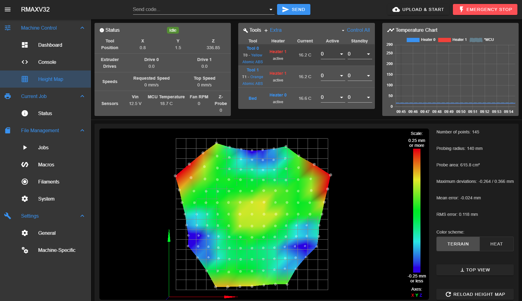
BuilTak system on Glass:
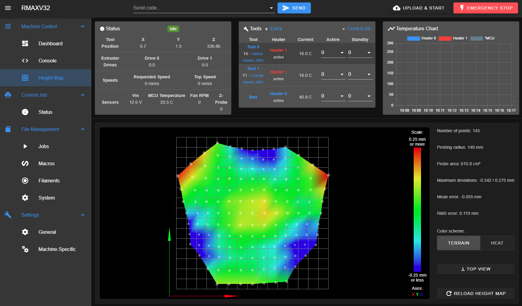
These are generated by the First Probe macro given by SeeMeCNC:
mesh results 145 points probed, min error -0.342, max error 0.275, mean -0.055, deviation 0.119
Height map saved to file heightmap.csvcal results Calibrated 6 factors using 19 points, deviation before 0.181 after 0.160
M291 P"FIRST PROBE PRINTER SETUP: Did you delete heightmap.csv and config-override.g?  Continue Click OK" R"SETUP PRINTER" S3
M117 Begin RostockMAX v3.2 Initial Calibration
M117 Heating Bed Please Wait
M190 S70
M104 S0
M140 S0
M117 Heat Off - Starting Autolevel Keep Clear
M558 P5 I0 A1 S0.05 R0.4 H20 F1200
G32
M500
M117 Bed Mapping
M558 P5 I0 A1 S0.05 R0.4 H20 F1200
M117 Heating Bed Please Wait
M190 S70
M140 S0
G29
M500
G28
M84
M375
M117 End RostockMAX v3.2 Initial Calibration
This is performed on a fresh flash of 2.05_1 with DWC 2.07 see
M122M122 === Diagnostics === RepRapFirmware for Duet 2 WiFi/Ethernet version 2.05.1 running on Duet Ethernet 1.02 or later Board ID: 08DGM-917NK-F2MSW-6JKDG-3S86S-KZ5JD Used output buffers: 4 of 24 (18 max) === RTOS === Static ram: 25712 Dynamic ram: 92516 of which 108 recycled Exception stack ram used: 424 Never used ram: 12312 Tasks: NETWORK(ready,572) HEAT(blocked,1232) MAIN(running,364) IDLE(ready,160) Owned mutexes: === Platform === Last reset 10:43:17 ago, cause: power up Last software reset at 2020-04-10 18:10, reason: User, spinning module GCodes, available RAM 12304 bytes (slot 2) Software reset code 0x0003 HFSR 0x00000000 CFSR 0x00000000 ICSR 0x0441f000 BFAR 0xe000ed38 SP 0xffffffff Task 0x4e49414d Error status: 0 Free file entries: 9 SD card 0 detected, interface speed: 20.0MBytes/sec SD card longest block write time: 8.6ms, max retries 0 MCU temperature: min 16.7, current 19.4, max 24.1 Supply voltage: min 12.3, current 12.4, max 12.7, under voltage events: 0, over voltage events: 0, power good: yes Driver 0: standstill, SG min/max 0/642 Driver 1: standstill, SG min/max 0/654 Driver 2: standstill, SG min/max 0/1023 Driver 3: standstill, SG min/max not available Driver 4: standstill, SG min/max not available Date/time: 2020-04-12 10:06:47 Cache data hit count 4294967295 Slowest loop: 29.28ms; fastest: 0.06ms I2C nak errors 0, send timeouts 0, receive timeouts 0, finishTimeouts 0, resets 0 === Move === Hiccups: 0, FreeDm: 160, MinFreeDm: 157, MaxWait: 37089207ms Bed compensation in use: mesh, comp offset 0.000 === DDARing === Scheduled moves: 513, completed moves: 513, StepErrors: 0, LaErrors: 0, Underruns: 0, 0 === Heat === Bed heaters = 0 -1 -1 -1, chamberHeaters = -1 -1 Heater 0 is on, I-accum = 0.4 Heater 1 is on, I-accum = 0.0 === GCodes === Segments left: 0 Stack records: 3 allocated, 1 in use Movement lock held by null http is doing "M190 S70" in state(s) 0 0 telnet is idle in state(s) 0 file is idle in state(s) 0 serial is idle in state(s) 0 aux is idle in state(s) 0 daemon is idle in state(s) 0 queue is idle in state(s) 0 autopause is idle in state(s) 0 Code queue is empty. === Network === Slowest loop: 8.99ms; fastest: 0.02ms Responder states: HTTP(0) HTTP(0) HTTP(0) HTTP(0) FTP(0) Telnet(0) Telnet(0) HTTP sessions: 1 of 8 Interface state 5, link 100Mbps full duplexThe hardware is 1.8 degree steppers plus 20T pulleys from the original ready to print V3 with aSE300 hot end that is basically a Duet Smart Effector, carbon arms and milled ball joints from SeeMeCNC, and a duel extruder 2to1 package. The changes from my working RAMPS1.4 config are the Duet 2 and the SE300 hotend and wiring harness.
config.g
M550 PRMAXV32                              ; Printer name
M555 P2                                    ; Gcode Output Type
M552 S1                                    ; Enable Networking
M575 P1 B57600 S1                          ; PanelDue Comm Setup
G21                                        ; Work in millimetres
G90                                        ; Send absolute coordinates

M569 P0 S0                                 ; Drive 0 goes forwards (X)
M569 P1 S0                                 ; Drive 1 goes forwards (Y)
M569 P2 S0                                 ; Drive 2 goes forwards (Z)
M569 P3 S0                                 ; Drive 3 goes forwards (E0)
M569 P4 S0                                 ; Drive 4 goes forwards (E1)

M574 X2 Y2 Z2 S1                           ; set endstop configuration (all endstops at high end, active high)

;M665 R144 L291.06 B135 H400 X0 Y0 Z0       ; delta radius, diagonal rod length, printable radius and homed height
M665 R144 L377 B135 H340 X0 Y0 Z0         ; optional carbon fiber arms length setting
                                           ; Y X Z are tower angle offsets
M666 X0 Y0 Z0                              ; endstop offsets in mm

M350 X16 Y16 Z16 E16:16 I1                 ; Set 16x microstepping w/ Interpolation
;M92 X200 Y200 Z200                         ; Set axis steps/mm for .9 motor with 16T pulley
M92 X80 Y80 Z80								; Set axis steps/mm for 1.8 motor with 20T pulley (org v3 config)
;M92 E182.0:182.0                           ; Set extruder steps/mm for .9 motor for EZR Extruder
M92 E91.0:91.0								; set extruder steps/mm for 1.8 motor for EXR Extruder

M906 X1200 Y1200 Z1200 E1200:1200 I50      ; Set motor currents (mA) and idle current %
M201 X4200 Y4200 Z4200 E5000               ; Accelerations (mm/s^2)
M203 X15000 Y15000 Z15000 E15000           ; Maximum speeds (mm/min)
M566 X2000 Y2000 Z2000 E2000               ; Maximum instant speed changes mm/minute

M106 P0 H-1                                ; Part Cooling Fan
M106 P1 S0.5 H-1                           ; Case fan
M106 P2 T50 S0.7 H1                        ; Heat sink fan

M307 H0 B0                                 ; Heated Bed (H2)
M305 P0 T100000 B4388 R4700 H30 L0         ; Bed thermistor

M305 P1 T100000 B4388 R4700 C7.06e-8 H30 L0      ; Hotend Thermistor
M563 P0 D0 H1                              ; Hot end (T0), drive (E0), heater (H1)
G10 P0 S0 R0                               ; Hot end operating and standby temperatures

;Dual Extrusion Code
M563 P1 D1 H1                              ; Hot end (T1), drive (E1), heater (H1)
G10 P1 S0 R0                               ; Hot end (1) operating and standby temperatures

M558 P5 I0 A10 S0.05 R0.4 H5 F1200         ; Strain gauge probe settings
G31 P100 X0 Y0 Z-0.3                       ; Probe trigger and offset values
M557 R140 S20                              ; default bed mapping
M501                                       ; Load saved config values
T0                                         ; Select Tool 0
M375									   ; Load height map
CONTINUED IN NEXT POST
-
So here are the rest of the config that I think might be helpful. If you want pictures of the hardware let me know and I can take some video or pictures.
bed.g
M203 Z15000
G28

M109 S0
M140 S0
M106 P0 S0
M106 P2 S0 H-1

G30 P0 X0 Y134.9 H0 Z-99999
G30 P1 X67.45 Y116.83 H0 Z-99999
G30 P2 X116.83 Y67.45 H0 Z-99999
G30 P3 X134.9 Y0 H0 Z-99999
G30 P4 X116.83 Y-67.45 H0 Z-99999
G30 P5 X67.45 Y-116.83 H0 Z-99999
G30 P6 X0 Y-134.9 H0 Z-99999
G30 P7 X-67.45 Y-116.83 H0 Z-99999
G30 P8 X-116.83 Y-67.45 H0 Z-99999
G30 P9 X-134.9 Y0 H0 Z-99999
G30 P10 X-116.83 Y67.45 H0 Z-99999
G30 P11 X-67.45 Y116.83 H0 Z-99999
G30 P12 X0 Y67.4 H0 Z-99999
G30 P13 X58.37 Y33.7 H0 Z-99999
G30 P14 X58.37 Y-33.7 H0 Z-99999
G30 P15 X0 Y-67.4 H0 Z-99999
G30 P16 X-58.37 Y-33.7 H0 Z-99999
G30 P17 X-58.37 Y33.7 H0 Z-99999
G30 P18 X0 Y0 H0 Z-99999 S6

M106 P2 T50 S0.5 H1

G28
homedelta.g
M203 Z15000
G91                         ; use relative positioning
G1 S1 X750 Y750 Z750 F5000  ; move all carriages up, stopping at the endstops
G1 S2 X-5 Y-5 Z-5 F500     ; move all towers down 5mm
G1 S1 X8 Y8 Z8 F500        ; move towers slowly up 8mm, stopping at the endstops
G1 S2 X-5 Y-5 Z-5 F500     ; move carriages down 5mm
G90                         ; back to absolute positioning
config-override.g
; config-override.g file generated in response to M500 at 2020-04-11 23:36
; This is a system-generated file - do not edit
; Delta parameters
M665 L377.000:377.000:377.000 R150.140 H341.958 B135.0 X-0.281 Y-0.148 Z0.000
M666 X-0.605 Y-0.037 Z0.642 A0.00 B0.00
; Heater model parameters
M307 H0 A90.0 C700.0 D10.0 S1.00 V0.0 B0
M307 H1 A340.0 C140.0 D5.5 S1.00 V0.0 B0
M307 H2 A340.0 C140.0 D5.5 S1.00 V0.0 B0
M307 H3 A340.0 C140.0 D5.5 S1.00 V0.0 B0
M307 H4 A340.0 C140.0 D5.5 S1.00 V0.0 B0
M307 H5 A340.0 C140.0 D5.5 S1.00 V0.0 B0
M307 H6 A340.0 C140.0 D5.5 S1.00 V0.0 B0
M307 H7 A340.0 C140.0 D5.5 S1.00 V0.0 B0
G10 L2 P1 X0.00 Y0.00 Z0.00
G10 L2 P2 X0.00 Y0.00 Z0.00
G10 L2 P3 X0.00 Y0.00 Z0.00
G10 L2 P4 X0.00 Y0.00 Z0.00
G10 L2 P5 X0.00 Y0.00 Z0.00
G10 L2 P6 X0.00 Y0.00 Z0.00
G10 L2 P7 X0.00 Y0.00 Z0.00
G10 L2 P8 X0.00 Y0.00 Z0.00
G10 L2 P9 X0.00 Y0.00 Z0.00
heightmap.csv
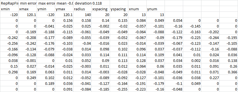 code_text ```RepRapFirmware height map file v2 generated at 2020-04-11 23:36 min error -0.264 max error 0.366 mean -0.024 deviation 0.118 xmin xmax ymin ymax radius xspacing yspacing xnum ynum -120 120.1 -120 120.1 140 20 20 13 13 0 0 0 0.156 0.158 0.14 0.135 0.084 0.049 0.054 0 0 0 0 0 -0.041 -0.025 0.025 -0.002 -0.02 -0.057 -0.101 -0.16 -0.145 0 0 0 -0.169 -0.188 -0.115 -0.061 -0.049 -0.049 -0.064 -0.088 -0.122 -0.163 -0.202 0 -0.242 -0.208 -0.177 -0.089 -0.055 -0.039 -0.052 -0.067 -0.09 -0.179 -0.225 -0.264 -0.195 -0.256 -0.242 -0.176 -0.103 -0.04 -0.016 0.023 -0.014 -0.039 -0.067 -0.123 -0.147 -0.105 -0.166 -0.134 -0.079 -0.038 0.014 0.098 0.102 0.096 0.037 -0.037 -0.112 -0.16 -0.088 -0.096 -0.128 -0.088 -0.024 0.033 0.114 0.111 0.114 0.109 0.041 0.01 0.024 0.036 0.038 -0.001 0 0.01 0.052 0.09 0.113 0.128 0.037 0.034 0.002 0.016 0.138 0.15 0.027 -0.014 -0.025 -0.003 0.011 0.012 0.064 0.06 0.035 0.011 0.091 0.26 0.298 0.169 0.063 0.011 0.014 -0.003 -0.028 -0.028 -0.048 -0.049 0.011 0.071 0.366 0 0.249 0.102 0.012 -0.052 -0.089 -0.092 -0.127 -0.101 -0.036 0.038 0.227 0 0 0 0.189 0.036 -0.041 -0.127 -0.164 -0.191 -0.179 -0.1 0.049 0 0 0 0 0 0.091 -0.084 -0.185 -0.255 -0.223 -0.16 -0.048 0 0 0 -
Have you gone through this in close detail? https://duet3d.dozuki.com/Wiki/Calibrating_a_delta_printer
-
@Baenwort This is a good page for visualising what the effect of incorrectly set rod lengths and delta radius does: http://boim.com/DeltaUtil/CalDoc/Calibration.html
I'd say you have a mix of both causing your strange mesh pattern. I notice that the radius has jumped from R144 (in your config.g) to R150.140. I guess you've done a calibration but fixed the arm length? Are you sure that's the correct arm length? Because the mesh map points to either the arms being too short and the radius to large (which I think is more likely), or the other way around. At least the bed mesh map is pretty symmetrical, so I think adjusting these will get you a pretty flat bed.
Also, see guide @Phaedrux posted.
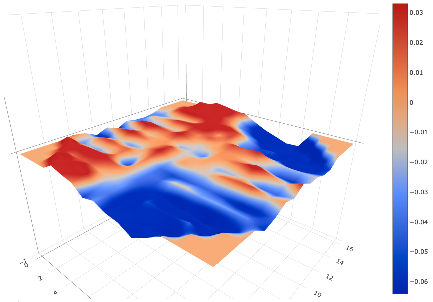
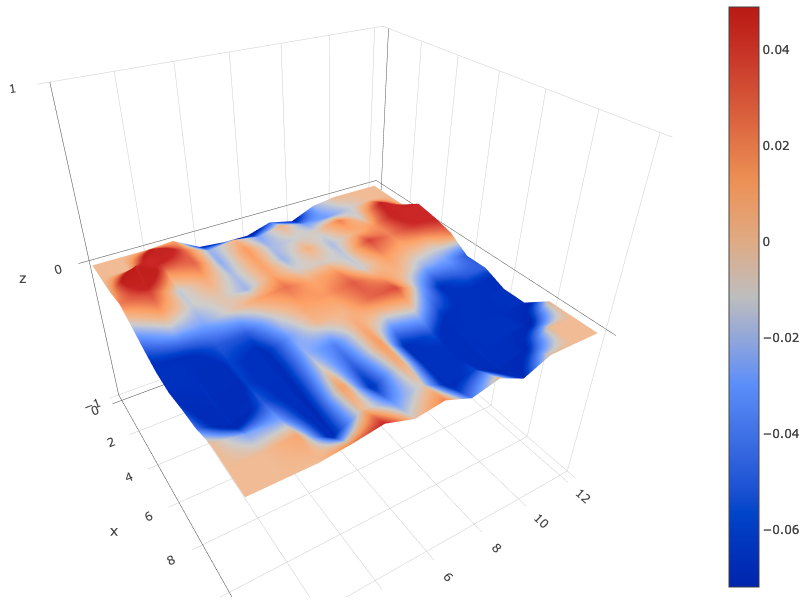
Edit: also found this, so I could look at your bed mesh in 3D using the csv data:
http://lokspace.eu/3d-printer-auto-bed-leveling-mesh-visualizer/Ian
Bed-slinger - Mini5+ WiFi/1LC | RRP Fisher v1 - D2 WiFi | Polargraph - D2 WiFi | TronXY X5S - 6HC/Roto | CNC router - 6HC | Tractus3D T1250 - D2 Eth
-
@droftarts The R value is 144 per the manufacturer suggestion but the actual build plate is 310mm diameter. I can try my best to measure the Delta Radius as I do have a device of sufficient size for that.
The arm length is beyond my ability to measure accurately as I don't have a tool that can do so. I rely on SeeMeCNC , a Duet3D partner manufacturer, to have made the arms and provided a accurate value. Which direction would you suggest adjusting and in what amount? Increase the arm length by 1mm?
That page does have some interesting information.
@Phaedrux I will give it a try. The idea of the first probe macro, provided by SeeMeCNC, is to do all those things. When upgrading to Duet from RAMPS the only changes are the Duet and the new hot end (which probes and connects in the same fashion between the two version) there are no physical changes and the printer has been successfully printing before this change. I changed mostly as I was having memory space issues with the RAMPS board and complex duel extrusion gcodes.
I'll report back after measuring the Delta Radius. Please make any other suggestions you'd like as I've spent the weekend and have exhausted my ideas.
-
So I did @Phaedrux 's instructions and physically everything seems to be as good as it was before the upgrade to Duet and SE300.
@droftarts I edited my rod lengths to 340.5 (which is what SeeMeCNC lists in https://www.seemecnc.com/products/carbon-fiber-arms-340-5mm-set-of-six and their own Wiki page. It is only in the github repo for their SD card load that it uses 377 for the arm length.
Since doing this I seem to have better results.
config-overide.g
; config-override.g file generated in response to M500 at 2020-04-12 22:39
; This is a system-generated file - do not edit
; Delta parameters
M665 L340.500:340.500:340.500 R141.959 H341.785 B135.0 X-0.283 Y-0.199 Z0.000
M666 X-0.530 Y-0.090 Z0.619 A0.00 B0.00
; Heater model parameters
M307 H0 A90.0 C700.0 D10.0 S1.00 V0.0 B0
M307 H1 A340.0 C140.0 D5.5 S1.00 V0.0 B0
M307 H2 A340.0 C140.0 D5.5 S1.00 V0.0 B0
M307 H3 A340.0 C140.0 D5.5 S1.00 V0.0 B0
M307 H4 A340.0 C140.0 D5.5 S1.00 V0.0 B0
M307 H5 A340.0 C140.0 D5.5 S1.00 V0.0 B0
M307 H6 A340.0 C140.0 D5.5 S1.00 V0.0 B0
M307 H7 A340.0 C140.0 D5.5 S1.00 V0.0 B0
G10 L2 P1 X0.00 Y0.00 Z0.00
G10 L2 P2 X0.00 Y0.00 Z0.00
G10 L2 P3 X0.00 Y0.00 Z0.00
G10 L2 P4 X0.00 Y0.00 Z0.00
G10 L2 P5 X0.00 Y0.00 Z0.00
G10 L2 P6 X0.00 Y0.00 Z0.00
G10 L2 P7 X0.00 Y0.00 Z0.00
G10 L2 P8 X0.00 Y0.00 Z0.00
G10 L2 P9 X0.00 Y0.00 Z0.00
and the heightmap:
RepRapFirmware height map file v2 generated at 2020-04-12 22:44, min error -0.127, max error 0.115, mean -0.025, deviation 0.048
xmin,xmax,ymin,ymax,radius,xspacing,yspacing,xnum,ynum
-120.00,120.10,-120.00,120.10,140.00,20.00,20.00,13,13
      0,      0,      0,  0.023, -0.013, -0.051, -0.083, -0.090, -0.063, -0.045,      0,      0,      0
      0,      0,  0.115,  0.042,  0.014, -0.023, -0.079, -0.120, -0.126, -0.104, -0.027,      0,      0
      0,  0.090,  0.019, -0.014, -0.013, -0.026, -0.055, -0.064, -0.065, -0.054, -0.028,  0.010,      0
  0.011,  0.030,  0.030,  0.008, -0.004, -0.007, -0.055, -0.083, -0.085, -0.085, -0.083, -0.077,  0.020
 -0.078, -0.022, -0.024, -0.018, -0.021,  0.011, -0.012, -0.029, -0.022, -0.008,  0.013, -0.000,  0.049
 -0.094,  0.001,  0.015,  0.012,  0.011,  0.026,  0.012,  0.002, -0.040, -0.052, -0.070, -0.033, -0.005
 -0.096, -0.027, -0.019, -0.021, -0.009,  0.009,  0.016,  0.003,  0.009,  0.015,  0.008, -0.008,  0.022
 -0.049,  0.003, -0.012,  0.005, -0.009,  0.016,  0.033,  0.029, -0.020, -0.075, -0.076, -0.082, -0.041
 -0.086, -0.030, -0.008, -0.018, -0.014, -0.013,  0.012,  0.037, -0.009, -0.059, -0.081, -0.061,  0.001
 -0.021, -0.030,  0.022,  0.004,  0.039,  0.015,  0.001, -0.022, -0.056, -0.099, -0.127, -0.123, -0.072
      0, -0.014, -0.011,  0.018,  0.022,  0.004, -0.022, -0.073, -0.078, -0.095, -0.114, -0.080,      0
      0,      0,  0.057,  0.065,  0.046,  0.000, -0.029, -0.055, -0.085, -0.118, -0.098,      0,      0
      0,      0,      0,  0.074,  0.054,  0.023, -0.054, -0.052, -0.103, -0.102,      0,      0,      0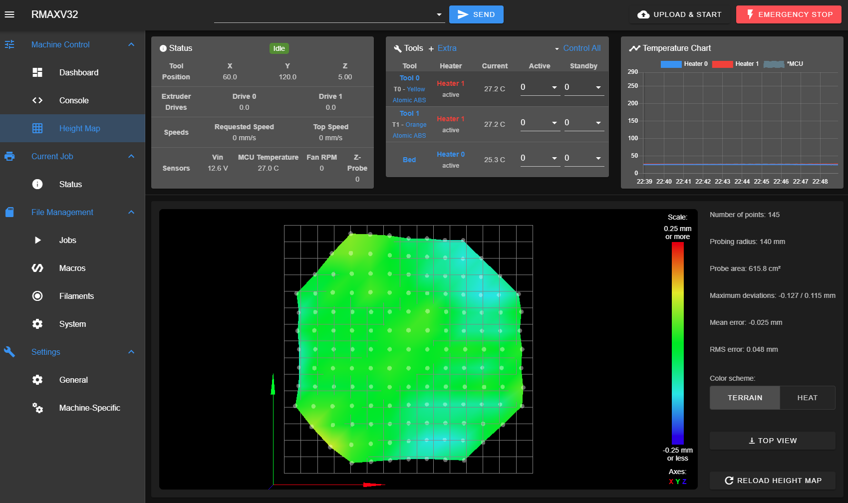
it still has the kinda strange curl in the three corners and a dip between them and the center slightly raised but this is within a range that I am going to try printing.
I will bring the 300mm micrometer home from work tomorrow and measure the Delta Radius as you requested. If you have other suggestions please make them as I'd like to get this all nailed down and the printer processing all the requests I have from friends and co-workers to make some of the NIH items.
-
@Baenwort Looks much better! There's still the shape there was before, but much subtler, so maybe it's just tweaking the arm length and delta radius now. I think there's also some effector tilt going on, or backlash in one of the axes, as you're getting alternate up/down lines in the X axis direction:
Have you tried running a 7-factor bed calibration? This will tune the arm lengths too.
It's very difficult to measure delta radius, and you need to measure the effector radius too:
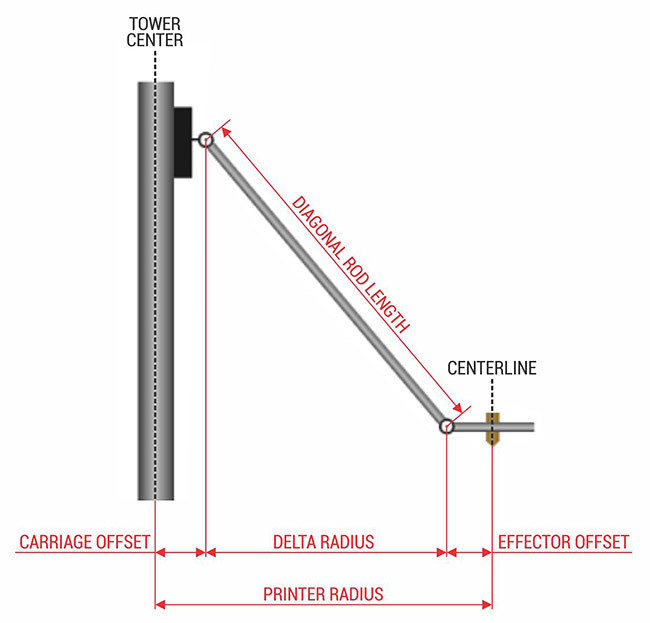
As you're so close, I'd just let the calibration sort it out.
Ian
Bed-slinger - Mini5+ WiFi/1LC | RRP Fisher v1 - D2 WiFi | Polargraph - D2 WiFi | TronXY X5S - 6HC/Roto | CNC router - 6HC | Tractus3D T1250 - D2 Eth
-
@droftarts I see that given what I have available to measure with it will be difficult as I'm not sure how precisely I would be able to measure from center to center of a open circle. The Effector wouldn't be as hard as I'd have the nozzle to align with and the extruded towers have a center channel I could also use.
Do you suggest tweaking by .5mm or even .1 in a given direction? I don't think the delta radius is the problem but rather the arm length. I've put in a issue on SeeMeCNC's github about this: https://github.com/seemecnc/RostockMaxV3.2/issues/2
I wasn't sure if I could do a S7 calibration as the wiki advice is that you need to be significantly outside the triangle of the towers and I don't think my surface is big enough?


The idea of the carbon arms and milled ball joints was to reduce backlash. I wish I had some more precision to measure tilt as the bubble levels and analog angle gauge I have don't show any issue. Would you suggest anything other then using a bubble level on the effector?


Is there a video host that would be best for me to post a G29 run or other movement video while the bubble ridges the effector?
-
@Baenwort said in Weird Bed Mesh - Delta - Rostock 3.2:
Is there a video host that would be best for me to post a G29 run
Dropbox, vimeo, youtube, google drive
-
@Baenwort In the end, the effector tilt is tiny, I'd say about 0.025mm. It may just be belt tension (equally tension all three belts), or a slight movement/sticking in an X-carriage, or stiction (static friction, ie that some force is needed to move them) in the ball joints. Did you lubricate the ball joints as recommended?
The bigger issue (and again, it's still pretty small, as your max deviation is +/- 0.125mm) is the delta radius and rod length, but I think these are close, and you're not going to get closer by physically measuring it.
I'd say yes, your bed is big enough to use S7 (or S8 or S9, though the bed looks pretty flat). I'd see what they report; you don't have to implement them. Just run them (adjust bed.g so the nozzle probes as close to the edge of the bed as possible, without hitting the towers) and run a bed mesh afterwards, to see if there's an improvement.
Ian
Bed-slinger - Mini5+ WiFi/1LC | RRP Fisher v1 - D2 WiFi | Polargraph - D2 WiFi | TronXY X5S - 6HC/Roto | CNC router - 6HC | Tractus3D T1250 - D2 Eth
-
@droftarts Thanks, I will try driving the nozzle over to the edge of the bed and measuring the coordinates to put into a extra points. I currently have the following bed.g
M203 Z15000
G28

M109 S0
M140 S0
M106 P0 S0
M106 P2 S0 H-1

G30 P0 X0 Y134.9 H0 Z-99999
G30 P1 X67.45 Y116.83 H0 Z-99999
G30 P2 X116.83 Y67.45 H0 Z-99999
G30 P3 X134.9 Y0 H0 Z-99999
G30 P4 X116.83 Y-67.45 H0 Z-99999
G30 P5 X67.45 Y-116.83 H0 Z-99999
G30 P6 X0 Y-134.9 H0 Z-99999
G30 P7 X-67.45 Y-116.83 H0 Z-99999
G30 P8 X-116.83 Y-67.45 H0 Z-99999
G30 P9 X-134.9 Y0 H0 Z-99999
G30 P10 X-116.83 Y67.45 H0 Z-99999
G30 P11 X-67.45 Y116.83 H0 Z-99999
G30 P12 X0 Y67.4 H0 Z-99999
G30 P13 X58.37 Y33.7 H0 Z-99999
G30 P14 X58.37 Y-33.7 H0 Z-99999
G30 P15 X0 Y-67.4 H0 Z-99999
G30 P16 X-58.37 Y-33.7 H0 Z-99999
G30 P17 X-58.37 Y33.7 H0 Z-99999
G30 P18 X0 Y0 H0 Z-99999 S6

M106 P2 T50 S0.5 H1

G28
How many points would you recommend? I am currently going to add 6 more points to the 18 I currently have. Three, each at the base of each tower, as close as I can maneuver the effector; and three, each directly opposite a tower, as far as I can position the nozzle out and still have solid bed under it.
Would that be sufficient for a S7?
I have lubed and cleaned and lubed again the ball joints on both the trucks and the effector ends with the white lube that SeeMeCNC gave with the ball joints. I've noticed that the lube likes to pick up dust and I never found a good recommendation on how much so I think I'm over lubricating out of caution.
-
So I made up some extra bed.g points, that after I modded my config.g to have a B150 in my definition area to let me get closer to the edge, gave me the following bed.g that did not crash anything and reached where I had hoped.
M203 Z15000
G28

M109 S0
M140 S0
M106 P0 S0
M106 P2 S0 H-1

G30 P0 X0 Y134.9 H0 Z-99999
G30 P1 X67.45 Y116.83 H0 Z-99999
G30 P2 X116.83 Y67.45 H0 Z-99999
G30 P3 X134.9 Y0 H0 Z-99999
G30 P4 X116.83 Y-67.45 H0 Z-99999
G30 P5 X67.45 Y-116.83 H0 Z-99999
G30 P6 X0 Y-134.9 H0 Z-99999
G30 P7 X-67.45 Y-116.83 H0 Z-99999
G30 P8 X-116.83 Y-67.45 H0 Z-99999
G30 P9 X-134.9 Y0 H0 Z-99999
G30 P10 X-116.83 Y67.45 H0 Z-99999
G30 P11 X-67.45 Y116.83 H0 Z-99999
G30 P12 X0 Y67.4 H0 Z-99999
G30 P13 X58.37 Y33.7 H0 Z-99999
G30 P14 X58.37 Y-33.7 H0 Z-99999
G30 P15 X0 Y-67.4 H0 Z-99999
G30 P16 X-58.37 Y-33.7 H0 Z-99999
G30 P17 X-58.37 Y33.7 H0 Z-99999
G30 P18 X-120 Y-70 H0 Z-99999 ;Xtower Base
G30 P19 X120 Y-70 H0 Z-99999 ;Ytower Base
G30 P20 X0 Y145 H0 Z-99999 ;Ztower Base
G30 P21 X132 Y70 H0 Z-99999 ;Xtower Cross
G30 P22 X-130 Y75 H0 Z-99999 ;Ytower Cross
G30 P23 X0 Y-150 H0 Z-99999 ;Ztower Cross
G30 P24 X0 Y0 H0 Z-99999 S9

M106 P2 T50 S0.5 H1

G28
This resulted in the following new config-overridge.g after three G32 runs followed by a M500.
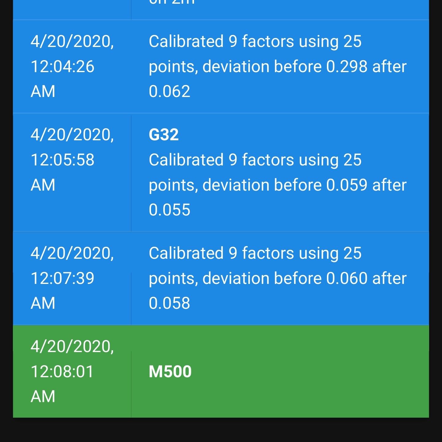
; config-override.g file generated in response to M500 at 2020-04-19 23:33
; This is a system-generated file - do not edit
; Delta parameters
M665 L342.562:342.562:342.562 R142.418 H342.097 B150.0 X-0.284 Y-0.224 Z0.000
M666 X-0.634 Y-0.553 Z1.187 A0.01 B0.25
; Heater model parameters
M307 H0 A90.0 C700.0 D10.0 S1.00 V0.0 B0
M307 H1 A340.0 C140.0 D5.5 S1.00 V0.0 B0
M307 H2 A340.0 C140.0 D5.5 S1.00 V0.0 B0
M307 H3 A340.0 C140.0 D5.5 S1.00 V0.0 B0
M307 H4 A340.0 C140.0 D5.5 S1.00 V0.0 B0
M307 H5 A340.0 C140.0 D5.5 S1.00 V0.0 B0
M307 H6 A340.0 C140.0 D5.5 S1.00 V0.0 B0
M307 H7 A340.0 C140.0 D5.5 S1.00 V0.0 B0
G10 L2 P1 X0.00 Y0.00 Z0.00
G10 L2 P2 X0.00 Y0.00 Z0.00
G10 L2 P3 X0.00 Y0.00 Z0.00
G10 L2 P4 X0.00 Y0.00 Z0.00
G10 L2 P5 X0.00 Y0.00 Z0.00
G10 L2 P6 X0.00 Y0.00 Z0.00
G10 L2 P7 X0.00 Y0.00 Z0.00
G10 L2 P8 X0.00 Y0.00 Z0.00
G10 L2 P9 X0.00 Y0.00 Z0.00
I then ran a G29 and got this heightmap.csv
RepRapFirmware height map file v2 generated at 2020-04-19 23:42, min error -0.179, max error 0.085, mean -0.021, deviation 0.052 xmin,xmax,ymin,ymax,radius,xspacing,yspacing,xnum,ynum -120.00,120.10,-120.00,120.10,135.00,15.00,15.00,17,17 0, 0, 0, 0, 0.059, 0.030, 0.012, -0.058, -0.032, -0.072, -0.085, -0.136, -0.076, 0, 0, 0, 0 0, 0, 0, 0.085, 0.038, 0.061, 0.042, -0.032, -0.042, -0.085, -0.078, -0.083, -0.134, -0.082, 0, 0, 0 0, 0, 0.043, 0.015, 0.021, 0.020, -0.001, -0.013, -0.033, -0.087, -0.053, -0.063, -0.063, -0.046, -0.089, 0, 0 0, 0.068, 0.036, 0.052, 0.047, 0.039, 0.024, 0.003, -0.042, -0.059, -0.074, -0.107, -0.098, -0.131, -0.109, -0.071, 0 0.014, -0.034, -0.022, -0.030, -0.017, 0.011, -0.058, 0.006, -0.040, -0.044, -0.014, -0.011, -0.027, -0.026, -0.030, -0.036, -0.064 -0.005, -0.014, 0.020, 0.027, 0.015, 0.017, -0.014, 0.015, -0.044, -0.055, -0.051, -0.047, -0.047, -0.058, -0.073, -0.069, -0.041 -0.060, -0.075, -0.029, -0.014, -0.032, -0.021, 0.011, 0.037, -0.018, 0.004, -0.010, -0.011, 0.014, 0.021, 0.026, -0.006, 0.007 -0.021, 0.005, 0.028, 0.042, 0.021, 0.003, 0.006, 0.027, -0.014, -0.002, 0.003, -0.023, -0.023, -0.011, -0.044, -0.046, -0.021 -0.069, -0.036, -0.028, 0.003, -0.013, 0.001, 0.007, -0.025, -0.016, -0.037, 0.005, 0.008, 0.022, 0.048, 0.013, -0.010, 0.033 -0.020, 0.002, 0.040, 0.050, 0.027, 0.018, 0.038, 0.008, -0.017, -0.002, 0.009, 0.005, -0.013, -0.022, -0.053, -0.060, -0.017 -0.039, -0.039, -0.021, -0.024, -0.013, -0.014, 0.025, 0.009, 0.022, 0.003, 0.027, 0.019, 0.037, -0.007, -0.018, -0.023, -0.017 -0.046, -0.007, -0.005, 0.012, 0.032, 0.033, 0.036, 0.051, 0.002, 0.025, -0.038, -0.050, -0.071, -0.054, -0.092, -0.072, -0.051 -0.033, -0.036, -0.022, -0.010, -0.008, 0.002, 0.034, 0.038, 0.049, 0.024, -0.024, -0.057, -0.051, -0.092, -0.085, -0.081, -0.055 0, -0.014, 0.025, 0.041, 0.051, 0.041, 0.046, 0.024, 0.005, -0.027, -0.049, -0.096, -0.123, -0.098, -0.133, -0.085, 0 0, 0, 0.032, 0.038, 0.061, 0.048, 0.035, 0.009, -0.034, -0.060, -0.099, -0.114, -0.106, -0.122, -0.132, 0, 0 0, 0, 0, 0.080, 0.075, 0.071, 0.050, -0.002, -0.051, -0.079, -0.129, -0.149, -0.179, -0.158, 0, 0, 0 0, 0, 0, 0, 0.064, 0.049, 0.030, 0.020, -0.036, -0.089, -0.126, -0.164, -0.158, 0, 0, 0, 0 -
Have you verified the tower steps/mm? An error in the steps/mm setting has a similar effect to an error in the rod length, because it's the product of the two that needs to be right to get a flat print plane, assuming that the delta radius is adjusted to suit. Calibration with S7 gave you an increase in rod length from 340.5 to 342.5 which is abou 0.6%. If your real steps/mm is 0.6% smaller than the value you have used in config.g, that would have a similar effect.
Adjusting rod length or steps/mm will affect the scaling and geometry of printing. I suggest you print a maximum-size square, then check it for correct size and straight edges. Also print a large nought-and-crosses/tic-tac-toe pattern and check that the lines are parallel and correctly spaced.
Duet WiFi hardware designer and firmware engineer
Please do not ask me for Duet support via PM or email, use the forum
http://www.escher3d.com, https://miscsolutions.wordpress.com -
-
@dc42 I have 1.8 degree steppers with 20T pulleys from SeeMeCNC. Per their github and wiki this means I should be using 80 steps/mm for the axis and 91 steps/mm for the EZR Struders. This is what is in my config.g and I'm not sure if you are suggesting I should take 94% percent of 80 and use that?
I can switch out to. 9 steppers and 16T pulleys as I do have them on hand but I wanted to do this upgrade one component at a time.
-
I printed a large circle with crossing lines (the SeeMeCNC test wheel found at https://www.thingiverse.com/thing:3002657 or see my picture) and it measured well.
I am currently looking for a good large square that is the right size to fill the bed. How close to a full bed do I need? The bed is a 310mm circle but I don't plan to print larger than 280mm.
![20200425_230046[1].jpg](/assets/uploads/files/1587873860174-20200425_230046-1-resized.jpg)
![20200425_230228[1].jpg](/assets/uploads/files/1587873910145-20200425_230228-1-resized.jpg)
-
Did a 150mm square as that is the largest accurate measurement device I have.
Printed in ABS.

I don't understand what you mean by a toe print. Can you provide a reference I can scale in Cura?