Another BLTouch Topic
-
Good day to you fellows!
I thought I could get this to work on my own but now I'm at a point where I don't know how to solve this or what causes this problem.
I can't deploy or retract the probe nor do a selftest via M280 P7S120.
My Setup is a Duet WiFi 1.02 with a DueX2. I'm using the Firmware version 2.05.
The BLTouch is working and does a self test on startup.This is my second printer with a BLTouch and I've tested the Sensor with the wires hooked up to my second printer. It works!
If I detache the DueX2 and wire it directly to the H7 pin like in the description on betrue3d.dk and also Invert the signal it works perfect!
If I connect the DueX2 again, wire all up like I should and don't invert the signal it doesn't work.
deployprobe.g and retractprobe.g is in the sys folder.
Here is my config.g:
; General preferences
M111 S0 ; Debugging off
G21 ; Work in millimetres
G90 ; Send absolute coordinates...
M83 ; ...but relative extruder moves
M555 P1 ; Set firmware compatibility to look like RepRapFirmware; Machine Informations
M669 K1 ; Select CoreXY mode
M208 X0 Y0 Z0 S1 ; Set axis minima
M208 X400 Y225 Z250 S0 ; Set axis maxima; Endstops
M574 Z0 S2
M574 E0 S0 ; Set active low endstops
M574 X1 Y1 S1 ; Set active high endstops
M558 P9 X0 Y0 Z1 H5 F600 R0.05 A2 B0 T14000 ; Set Z Probe to type Switch or Digital output where Z probe connector is used. Used for z only.;Offset for E3D Nozzle
G31 P500 X0 Y100 Z0.0 ; Set Z probe trigger value, offset and trigger height; Drives
M569 P0 S1 ; Drive 0 goes forwards
M569 P1 S1 ; Drive 1 goes forwards
M569 P2 S1 ; Drive 2 goes forwards
M569 P3 S0 ; Drive 3 goes forwards
M569 P5 S1 ; Drive 5 goes forwards
M569 P6 S1 ; Drive 6 goes forwards;3-Z config
M584 Z2:5:6 ; Driver 2,5,6 for the three z-axis
M671 X-55:455:200 Y5:5:288 S10.0 ; defines leveling screw locationsM350 X16 Y16 Z16 E16 I1 ; Configure microstepping with interpolation
M92 X80 Y80 Z1600 ; Set steps per mm
;M92 E2700 ; Nimble
;M92 E418.35 ; Belted Extruder
;M92 E418.5 ; E3D Titan Aero
M92 E418 ; Bondtech BMG
M566 X500 Y500 Z200 E1200 ; Set maximum instantaneous speed changes (mm/min)
M203 X40000 Y40000 Z600 E12000 ; Set maximum speeds (mm/min)
M201 X3000 Y3000 Z200 E1500 ; Set accelerations (mm/s^2)
M906 X750 Y750 Z700 E700 I20 ; Set motor currents (mA) and motor idle factor in per cent
M84 S30 ; Set idle timeout; Heaters
M301 H0 S1.00 P10 I0.1 D200 T0.4 W180 B30 ; Use PID on bed heater (may require further tuning)
M305 P0 T100000 B3988 C0 R4700 ; Set thermistor + ADC parameters for heater 0
M143 H0 S120 ; Set temperature limit for heater 0 to 120C
M305 P1 T100000 B4725 C7.06e-8 ; Set thermistor + ADC parameters for heater 1
M143 H1 S310 ; Set temperature limit for heater 1 to 310C; Tools
M563 P0 D0 H1 F3 ; Define tool 0
G10 P0 X0 Y0 Z0 ; Set tool 0 axis offsets
G10 P0 R0 S0 ; Set initial tool 0 active and standby temperatures to 0C; Disable heaters for free PWM channels
M307 H7 A-1 C-1 D-1 ; Disable heater 7 for BLTouch PWM pin; Network
M550 Pbig_one ; Set machine name
M552 S1 ; Enable network
M586 P0 S1 ; Enable HTTP
M586 P1 S0 ; Disable FTP
M586 P2 S0 ; Disable Telnet; Fans
M106 P0 S255 I0 F400 H1 T45 ; Set fan 1 value, PWM signal inversion and frequency. Thermostatic control is turned on
;M106 P3 S0 I0 F400 ; Set fan 4 value, PWM signal inversion and frequency. Thermostatic control is turned on; Custom settings are not configured
M501
Also my config-override.g file:
; This is a system-generated file - do not edit
; Heater model parameters
M307 H0 A90.0 C700.0 D10.0 S1.00 V0.0 B1
M301 H0 P10.0 I0.100 D200.0
M307 H1 A438.1 C214.5 D6.0 S1.00 V24.1 B0Here you can see pictures of my wiring:
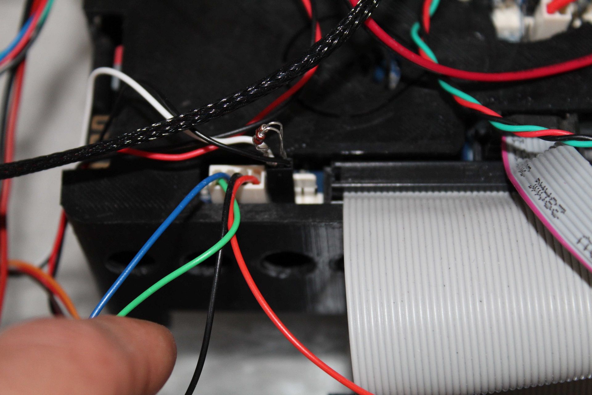
I Don't get it. What am I doing wrong?
I've read through all the post and reviewed my setup more then five times also I've done some test with a different board and without the DueX2.It would be very nice if someone could help me and point out what I'm doing wrong or not correct.
Kind regards
Andreas -
-
@The_Mechanic said in Another BLTouch Topic:
If I connect the DueX2 again, wire all up like I should and don't invert the signal it doesn't work.
Please post the content of deployprobe.g and retractprobe.g
Have you tried to invert the signal by editing this files? -
Changed the M574 parameters as you told me.
deployprobe.g
M280 P7 S10retractprobe.g
M280 P7 S90It's very crazy because the BLTouch does his selftest routine in the beginning so the wiring seems to be correct. If I write the commands via the console with and without I1 it doesn't do anything. Also the selftest via M280 P7 S120 doesn't work.
As I wrote in my first post. If I unplug the DueX2 and type the commands via the console it works.
Also I've changed the jumper position to 5V AUX.I don't know what to do more. O_o
-
@The_Mechanic said in Another BLTouch Topic:
Try PWM3 and change to P3 in your servo commands, Change to M307 H3 A-1 etc etc, and make sure there is no H3 entries in the config-override.
-
That's really strange. I've tested (like you told me) the first PWM port (PWM3) and it works. It works also with the PWM4. What makes me curious is that it doesn't work with PWM7.
If I don't change the config and only unplug the DueX2 and connect the BLTouch directly to the pin PWM7 on the connector it works (inverting the signal is necessary).
Isn't it strange?

For now it solves my problem, but I wan't to understand it and also to help others with this problem.
In first place I've to thank you very much Phaedrux! Great tip!
-
I've some news about my problem.
As @Phaedrux told me I've changed the PWM port to the first one on the DueX2 and it works since then.
Meanwhile I've updated to RRF 3. After I've set the config like the older one with RRF 2 it works again.Now I've thought why not testing it again, maybe it was a firmware problem?!
Here are the line out of my config.g
M950 S0 C"duex.pwm1" ; create servo pin 0 for BLTouch
M950 S2 C"duex.pwm4" ; create servo pin 0 for BLTouchI've two BLTouch's for testing. The first one works since the workaround and also on RRF 3.
After another test with PWM port 4 and 5 I come to the conclusion that it must be a hardware problem. PWM port 4 and 5 do not work.There is nothing in the config-override.g that could occupy the ports.
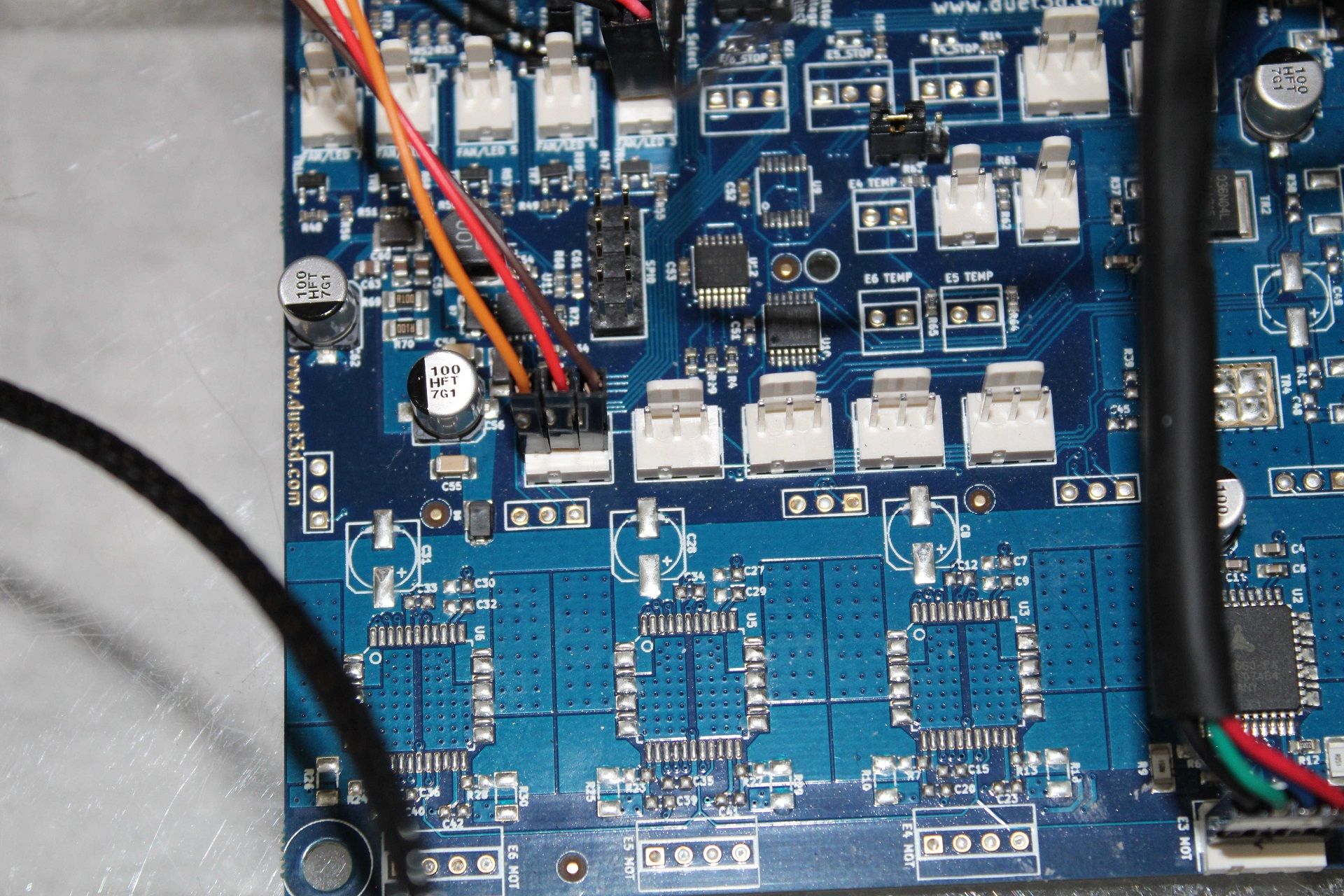
Here's also a picture of my DueX2.

Has someone a idea?
The workaround from @Phaedrux does work and solves the problem for me so this topic can be marked as solved.
-
@The_Mechanic said in Another BLTouch Topic:
PWM port 4 and 5 do not work.
How did you test that they do not work? Are you also using different M280 commands to reference the different pins?
-
@Phaedrux
I've sent M280 P2 S120 (BLTouch self test) through the console.
I don't change the P2 in my M280 command because the only change must be done in the config.g for the PWM port.M950 S2 C"duex.pwm4" (I've changed the '.pwm to .pwm2, 3, 4 etc.)
It works on the other ports.
The strange thing about these two PWM ports is that they have 5V (4.881 V measured with a multimeter).
There must be something wrong with the PWM signal.
-
@The_Mechanic There is a thread https://forum.duet3d.com/topic/10654/bl-touch-and-the-duex-5/65 at the posts starting 6th Nov 2019 of about PWM5 and a jumper, maybe this helps finding the reason.
-
@JoergS5
Thanks for that hint. This was a prolem I had in the past. But actually all ports do get 5V.
There must be something else wrong. -
@The_Mechanic your heater 6 is not blocked (because PWM5 and heater 6 share resources)?
Maybe your problem has something to do that your Duex 5 board has version 0.8. But I did not find something special yet (minor MOSFET ... changes).
-
@JoergS5
Don't get me wrong. It's a DueX2. I've read through these two boards and the only differences are the three TMC2660 that are not soldered. Am I right?I'm using the expansion board only because of my three z-axis, the BLTouch and two fans, that's all.
-
@The_Mechanic your image says Duex5:

Duex 2 is with 2 drivers, 5 with 5.
-
@JoergS5
Your're right. Thats wirtten on the board but it's a DueX2.M122
=== Diagnostics ===
RepRapFirmware for Duet 2 WiFi/Ethernet version 3.1.1 running on Duet WiFi 1.02 or later + DueX2
Board ID: 08DDM-9FAM2-LW4S4-6JTD6-3SJ6L-1LVRY
Used output buffers: 3 of 24 (23 max)I think thats because they share the same shematic.
-
@The_Mechanic thanks for explaining, this makes sense.
-
I've found something interesting.
@JoergS5 gave me a hint.My DueX2 is a version 0.8 and when I read the features section from the DueX2 and DueX5 I see this:
Duex 2 v0.8 and older
2 additional TMC2660 stepper motor drivers with stall notification.
2 additional extruder heater outputs.
2 servo outputs with 5V power and 5V signal levels, sharing control channels with the heaters. So you can use unused heater channels to drive servos.
2 additional endstop inputs with indicator LEDs and 3.3V/5V voltage selection. These are also usable as outputs.
6 additional PWM controlled fan outputs*, also usable for driving LEDs etc. The output voltage may be switched between 5V, 12V and VIN .
4 uncommitted general purpose I/O pins.
12V switching regulator, for generating a 12V supply for fans, LEDs etc. when the VIN power is higher than 12V.
2 additional thermistor inputs.
Support for 2 more thermocouple or PT100 daughter boards, supporting up to 4 more sensors.
Optional 5V external power input for powering servos, fans etc.
Duex 2 v0.8a and newer
2 additional TMC2660 stepper motor drivers with stall notification.
5 additional extruder heater outputs.
5 servo outputs with 5V power and 5V signal levels, sharing control channels with the heaters. So you can use unused heater channels to drive servos.
5 additional endstop inputs with indicator LEDs and 3.3V/5V voltage selection. These are also usable as outputs.
6 additional PWM controlled fan outputs, also usable for driving LEDs etc. The output voltage may be switched between 5V, 12V and VIN .
4 uncommitted general purpose I/O pins.
12V switching regulator, for generating a 12V supply for fans, LEDs etc. when the VIN power is higher than 12V.
5 additional thermistor inputs.
Support for 2 more thermocouple or PT100 daughter boards, supporting up to 4 more sensors.
Optional 5V external power input for powering servos, fans etc.
Now the crazy part. I have a 0.8 and not a 0.8a but I can use the servo ports 1-3. This is really strange and does not apply to any logic.
@dc42
May you could tell me where I'm wrong or misunderstand something?