External bearings for stepper shafts
-
@deckingman said in External bearings for stepper shafts:
@Nxt-1 said in External bearings for stepper shafts:
Stretch will indeed occur mostly when initially tensioning but even during movements the belt acts like a spring I would say. An extremely bad spring but a spring nonetheless. The resistance to motion on a delta would indeed be low, but at high accelerations the speak load on the belts is what worries me.
The theory is sound - I have no problem with that. But is it a problem in reality? How much do (pre-tensioned) belts stretch due to the force required to accelerate the mass? It obviously depends on many factors - the mass, the rate of acceleration, the resistance to stretching of the belt, the belt length etc. If the amount of "stretch" is immeasurably small or even in the 10s of microns range, then in reality I would suggest that it isn't a problem.
I can't say that I've noticed any print artefacts that could be attributed to belt stretchg on my 2Kg + gantry using 6mm belts. But then again, I only use 1000 mm/sec^2 acceleration so I might see some adverse effects if I increased that acceleration.
Yes the amount of stretch is impossible to measure, at least for me it is. That is why I initially opted for 9 mm belt, to ensure that there is noting that I can really to the make it better should it be a problem. I have seen it being a problem when doing straight up and down Z moves on my delta (normally 2000 mm/sec^2 acceleration). The nozzle effectively over travels. Now I must admit this could also be due to other parts not being rigid enough, or most likely a combination of all.
@deckingman said in External bearings for stepper shafts:
@Nxt-1 Is using a "remote motor" not possible on your machine?
I would have to look into it whether I can fit it (the new top compartment will be quite a bit smaller in the new design). But I am not really a fan of having to belts to tension, even if the 2nd belt need not be really tight.
-
@Nxt-1 said in External bearings for stepper shafts:
............... But I am not really a fan of having to belts to tension, even if the 2nd belt need not be really tight.
It could be a bit tricky but not impossible by any means. The way I tension my belts is to have the motors on sliding mounts so I'd do the same, and also have the "axel" on a sliding mount. The motor mount would be off to one side so it would slide left to right say, with the axel mount sliding front to back. Tension the main belt first, then do the motor. Something like that anyway........
Keep us posted on what you end up with.
-
The Z axis in my printer is lifted by two Gates LL2MR09 glass core belts. I checked stretch by stacking weight on the bed and measuring how much it dropped. Two belts in parallel stretched by 0.58 mm when loaded with 4 kg. The belts were tensioned, and already supporting the approximately 3.5 kg mass of the bed assembly before the extra weight was added.
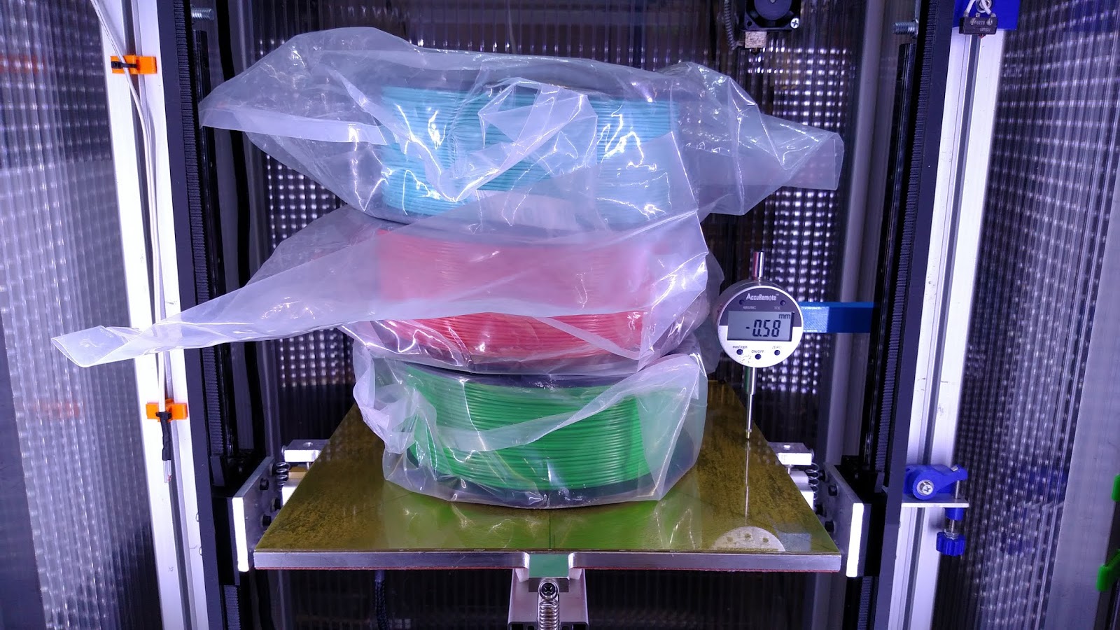
That seems like a lot of stretch, but it's an unrealistic load for the Z axis. I might one day make a 1 kg print, but don't expect to ever make a 4 kg print. Assuming that the stretch is a linear function of the applied load, that works out to a maximum of 4 um stretch in any print layer, assuming the layer is 0.25 mm thick and covers the entire 300x300 mm bed surface with PLA.
I used steel core belts prior to installing the glass core belts. With the same test they stretched about 1/3 as much.
The length of the belt that is stretching is about 1.2m- that is the total length of belt from the bed, up to the pulley at the top of the Z axis and back down to the drive pulley on the motor at the bottom of the Z axis.
-
@mrehorstdmd Useful to know.
Edit - if it was anyone else I'd question if the change could be due to flex in the frame or bed but I wouldn't dream of asking you that question.
-
@mrehorstdmd said in External bearings for stepper shafts:
The Z axis in my printer is lifted by two Gates LL2MR09 glass core belts. I checked stretch by stacking weight on the bed and measuring how much it dropped. Two belts in parallel stretched by 0.58 mm when loaded with 4 kg. The belts were tensioned, and already supporting the approximately 3.5 kg mass of the bed assembly before the extra weight was added.
That seems like a lot of stretch, but it's an unrealistic load for the Z axis. I might one day make a 1 kg print, but don't expect to ever make a 4 kg print. Assuming that the stretch is a linear function of the applied load, that works out to a maximum of 4 um stretch in any print layer, assuming the layer is 0.25 mm thick and covers the entire 300x300 mm bed surface with PLA.
I used steel core belts prior to installing the glass core belts. With the same test they stretched about 1/3 as much.
The length of the belt that is stretching is about 1.2m- that is the total length of belt from the bed, up to the pulley at the top of the Z axis and back down to the drive pulley on the motor at the bottom of the Z axis.
Awesome that you tested that, thanks for sharing. While I have 2kg prints in the past, the print doesn't move so it does not matter. My belts are quite a bit long though, the rails are already 1000mm long. I have not taken the belts out and measured them, but my guesstimate 2.3 m will not be far of.
I wish I could preform the same objective tests with static loads, but with a delta, the major load on the movement systems come from a moving mass that is the head.
-
Some average 400g extruder assembly in case of the direct-drive so with 1000mm/sec/sec acceleration (decent value to work with) we are talking about 0.4N force on the belt. With measured .5mm stretch for 40N force and assuming (I'm pretty sure it is not linear but since I have no clue what the actual relation is guesswork with linear is simplest
 ) linear relation we can assume (and @mrehorstdmd can actually measure) 0.4N will stretch the belt 0.005mm. No clue how movement of the one motor translate to movement of the effector (is 0.005mm movement of the thingidadud on one of the rails moved by motor translate to more or less than 0.005mm movement of the nozzle) but I doubt 0.005mm stretch can produce visible ringing. I am planing to do some comparison chart between few different belts, have a rig in mind but ... time ...
 -
@bot said in Delta stepper upgrade - advice welcome:
This might sound like a crazy suggestion...
What if you used two stepper motors? One of them disconnected, facing the other one, just as a support shaft? Basically, the amount that the drive pulley extends past the end of the motor shaft can be supported by the shaft of the other stepper.
Another crazy Idea: find a bearing block with a bearing ID large enough to go around the part of the pulley with the set screw. Support the pulley directly!
I'm full of crazy ideas.
Quoted from the parallel stepper motor thread.
You are crazy but I like it
") . The first thing that comes to mind with your suggestion is why do you need and second stepper. You are only interested in its axle and bearings. Only a second shaft with bearings will do the trick and is quite a bit cheaper. This is how I interpreted what you said, with my comment incorporated.
. The first thing that comes to mind with your suggestion is why do you need and second stepper. You are only interested in its axle and bearings. Only a second shaft with bearings will do the trick and is quite a bit cheaper. This is how I interpreted what you said, with my comment incorporated.
-
@Nxt-1 Could be tricky to get everything aligned properly I'd have thought. A bit of misalignment could end up putting more load on the motor bearings than just the belt tension if you didn't take great care.
-
@deckingman While we are in "crazy idea mode", how about a centre hole in the end of the motor shaft, then use something akin to a revolving centre? Like a live centre in the tail stock on a lathe which is used for the sole purpose of supporting the ends of long shafts to prevent them bending while being machined.
-
Here's a NEMA-17 motor with 30+ mm long shaft:
https://www.ebay.com/itm/NEW-Nema-17-Stepper-motor-76oz-in-w-FLAT-CNC-Robot-Reprap-Makerbot-Arduino-11V/321970627102?hash=item4af6f1e21e:g:~wsAAOSwBahU52GO -
@deckingman said in External bearings for stepper shafts:
@Nxt-1 Could be tricky to get everything aligned properly I'd have thought. A bit of misalignment could end up putting more load on the motor bearings than just the belt tension if you didn't take great care.
This is what I am afraid of with this idea as well. If you do not want to make to problem worse then it is, there is very little room for alignment errors.
@deckingman said in External bearings for stepper shafts:
@deckingman While we are in "crazy idea mode", how about a centre hole in the end of the motor shaft, then use something akin to a revolving centre? Like a live centre in the tail stock on a lathe which is used for the sole purpose of supporting the ends of long shafts to prevent them bending while being machined.
In this case if you really want support from a revolving center this small, my guess is that you would need to apply quite a bit of force axially, which would have to be accounted for by the steppers bearings. That is sadly what we are trying to eliminate
@mrehorstdmd said in External bearings for stepper shafts:
Here's a NEMA-17 motor with 30+ mm long shaft:
https://www.ebay.com/itm/NEW-Nema-17-Stepper-motor-76oz-in-w-FLAT-CNC-Robot-Reprap-Makerbot-Arduino-11V/321970627102?hash=item4af6f1e21e:g:~wsAAOSwBahU52GOA few remarks, I have kind of set my mind on nema 23 steppers at this point unless there is some really compelling reason to not do that. Second, that stepper is 1.8°, eliminating it for this project. Also the coil inductance is not specced and guessing from its 12V rating it will be quite high.
-
@Nxt-1 said in External bearings for stepper shafts:
there is very little room for alignment errors.
that's where those soft couplers come into play
you get the axle with bearings and pulley where they need to be, you link the axle with the motor using flex coupler, they transfer torque (small alu ones go up to 3Nm) will have no backlash and will allow slight misalignment between two shafts. Even the ghetto couplers we made 10 years ago out of the plastic tubing held pretty good for 3d printing purposes, they even work on the mill, flex couplers would totally work here -
@arhi said in External bearings for stepper shafts:
@Nxt-1 said in External bearings for stepper shafts:
there is very little room for alignment errors.
that's where those soft couplers come into play
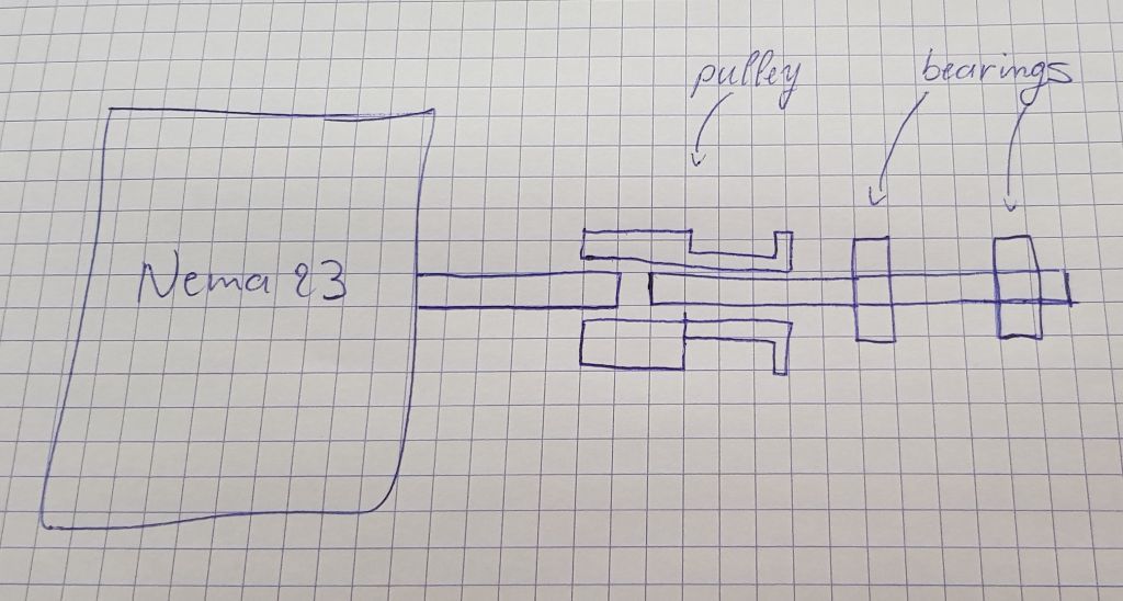
you get the axle with bearings and pulley where they need to be, you link the axle with the motor using flex coupler, they transfer torque (small alu ones go up to 3Nm) will have no backlash and will allow slight misalignment between two shafts. Even the ghetto couplers we made 10 years ago out of the plastic tubing held pretty good for 3d printing purposes, they even work on the mill, flex couplers would totally work hereWhat I understand you said is: stepper -> flex coupler -> 2nd shaft with bearings and pulley. If I got that correct then how does that differ from what I suggested in the first post of this thread?
-
@Nxt-1 said in External bearings for stepper shafts:
In this case if you really want support from a revolving center this small, my guess is that you would need to apply quite a bit of force axially, which would have to be accounted for by the steppers bearings. That is sadly what we are trying to eliminate
No - you misunderstand. I was thinking along the lines of a mini lathe tail stock with a revolving centre fitted. Actually, not as complicated as a tail stock - just a couple of bearing blocks to hold he centre. Essentially, it's like your diagram but instead of the pulley being the coupling between the two shafts you use a centre - doesn't even have to be a "live" revolving centre, it could be a dead (static) centre. It's difficult to explain if you've never used a lathe - take a gander at this https://www.youtube.com/watch?v=P5os5RRaG58
-
@Nxt-1 said in External bearings for stepper shafts:
What I understand you said is: stepper -> flex coupler -> 2nd shaft with bearings and pulley. If I got that correct then how does that differ from what I suggested in the first post of this thread?
exactly, exactly, sorry, long thread I forgot we started with that, but I don't see any reason not to go that way, it's commonly used in many professional machines
-
@Nxt-1 indeed, the bearings and shaft are all that we need. However, what's the cost of that? Is it the same as the motor that you are driving? I've seen legitimate motion control product development companies use a stepper with the wires cut off as a bearing block/idler shaft. It's sometimes cheaper than good fiddly bits, if those steppers are already purchased in volume.
I personally like better the even crazier idea of a bearing supporting the pulley.
*not actually a robot
-
While we are on the topic of crazy ideas... this one is good sit down.
You know how the ends of stepper motor shafts have little holes in the end? (at least, mine do. But they don't have D cuts either, so they aren't exactly typical.)
I think these are so that you can add a tapped hole to the end, to screw something to the end. Like, perhaps, a shaft extension?
Use an M3 stud (just a threaded shaft) to join the stepper motor (which you have tapped the end with M3 threads) and this.
lololol
*not actually a robot
-
@bot said in External bearings for stepper shafts:
@Nxt-1 indeed, the bearings and shaft are all that we need. However, what's the cost of that? Is it the same as the motor that you are driving? I've seen legitimate motion control product development companies use a stepper with the wires cut off as a bearing block/idler shaft. It's sometimes cheaper than good fiddly bits, if those steppers are already purchased in volume.
I personally like better the even crazier idea of a bearing supporting the pulley.
The only real issue with that is space, I believe I do not have space enough to add the length of a coupler in there. I would have to rotate my steppers 90°, so they are square to the tower extrusions. This would also require me to redesign the carriages to accommodate for the rotated belts.
I will double check my CAD files to see how much space I have without rotation.
@bot said in External bearings for stepper shafts:
While we are on the topic of crazy ideas... this one is good sit down.
You know how the ends of stepper motor shafts have little holes in the end? (at least, mine do. But they don't have D cuts either, so they aren't exactly typical.)
I think these are so that you can add a tapped hole to the end, to screw something to the end. Like, perhaps, a shaft extension?
Use an M3 stud (just a threaded shaft) to join the stepper motor (which you have tapped the end with M3 threads) and this.
lololol
That is not to bad of an idea, the issue is that I do not have the capabilities to drill and tap a hole in the stepper shaft, which might even be hardened. Lets alone that I can do it with the accuracy that is required in this case.
-
I just checked the CAD model, assuming 54 mm long steppers, they stick outside of the frame by 4.8 mm. That might be acceptable actually. I will think about it.
-
I got back from Oriental Motor with regards to my question if steppers with custom shaft are something they do. They do with a MOQ of 500/year, so no option.