External bearings for stepper shafts
-
@Nxt-1 said in External bearings for stepper shafts:
I think my plan of action is going to be in this order:
- Ask stepper manufactures if they will make me a stepper with a custom shaft (single shaft, extra long). If they will and for a reasonable price (which I strongly doubt) this is the route to go I think.
- Get a nema 23 dual shaft motor and try 9 mm belts with the corresponding pulleys. This leaves no room for an external bearing in front so the bearing idea is dropped. If the motor seems fine at highish tension, then were good.
- Use the motor from 2) and move to 6 mm belts with the corresponding smaller pulleys. This leaves room for an external bearing in front and back.
- Use the motor from 2) use a rigid coupler to a second shaft, where the pulley for 9 mm belts and two bearings sit on. Redesign the belt paths, carriages and rotate the steppers 90° so they are at a right angle to the tower extrusions.
I am not sure about 3) and 4), they might be swapped around as proper belts are not really cheap and redesigning the carriages only costs me time and effort.
- has been more or less crossed out and I currently debating to skip 2) and 3) and go straight to 4). Assuming that I go for single shaft steppers and stick to 54 mm long steppers at max I can fit a coupler and shaft with needing to rotate the whole shebang. I will start looking into steppers again in the motor thread, I expect to find quite few more options if dual shafts are not a requirement.
-
@bot said in External bearings for stepper shafts:
You know how the ends of stepper motor shafts have little holes in the end?
Normally ones without D shaft have those. I have bin told by a machinist that's 'cause you would normally heat press the pulley on that shaft (heat the pulley so it expand, put on the shaft, leave to cool of and grab the shaft) and to remove it you need to use the "radapcieger" (no idea what the english word is, but it's a puller). You attach 3 arms to the pulley and press the center in to the hole of the shaft and pull the pulley off. Without that hole it would be very hard to do it.
-
You could also turn the pulley 180 degrees on the shaft; the motor mount looks to be slotted, so after turning it around, you move the motor closer. The result is, there's less moment forces on the shaft, since the bearing point that's at the shell face. The greater distance from the bearing point, the greater the eccentric load on that shaft.
-
@arhi it's called a gear puller: https://duckduckgo.com/?q=gear+puller&t=peppermint&ia=images&iax=images
-
@mrehorstdmd said in External bearings for stepper shafts:
@arhi it's called a gear puller: https://duckduckgo.com/?q=gear+puller&t=peppermint&ia=images&iax=images
 yeah, thanks, I always forget the English name for it .. radapciger here and in Germany:D
https://duckduckgo.com/?q=radapciger&t=peppermint&iar=images&iax=images&ia=images -
I was considering something similar to mrehorstdmd. A bearing carrier with an idler bearing on the shaft above the pulley. Then I saw someone who went as crazy as me and did it. The additional tension he was able to apply to the motor was minimal, less than 5% before the tension on the belt system still stalled out the motors. 3 months later the bearings in his steppers and half his gates pulleys were shot. The best guess is that the extra tension caused the bearings in the pulleys to overheat, seize, and that transferred stress to every component in the drive system. I might still eventually do it, but it will be more to limit stepper shaft deflection during acceleration and speed changes. As for increased belt tension, I think you're better off keeping it simple and using bigger steppers AND idlers.
-

My solution, I know it is not perfect but works fine over hals a year. And before that I also broke my stepper motor shaft. -
@Nuramori said in External bearings for stepper shafts:
You could also turn the pulley 180 degrees on the shaft; the motor mount looks to be slotted, so after turning it around, you move the motor closer. The result is, there's less moment forces on the shaft, since the bearing point that's at the shell face. The greater distance from the bearing point, the greater the eccentric load on that shaft.
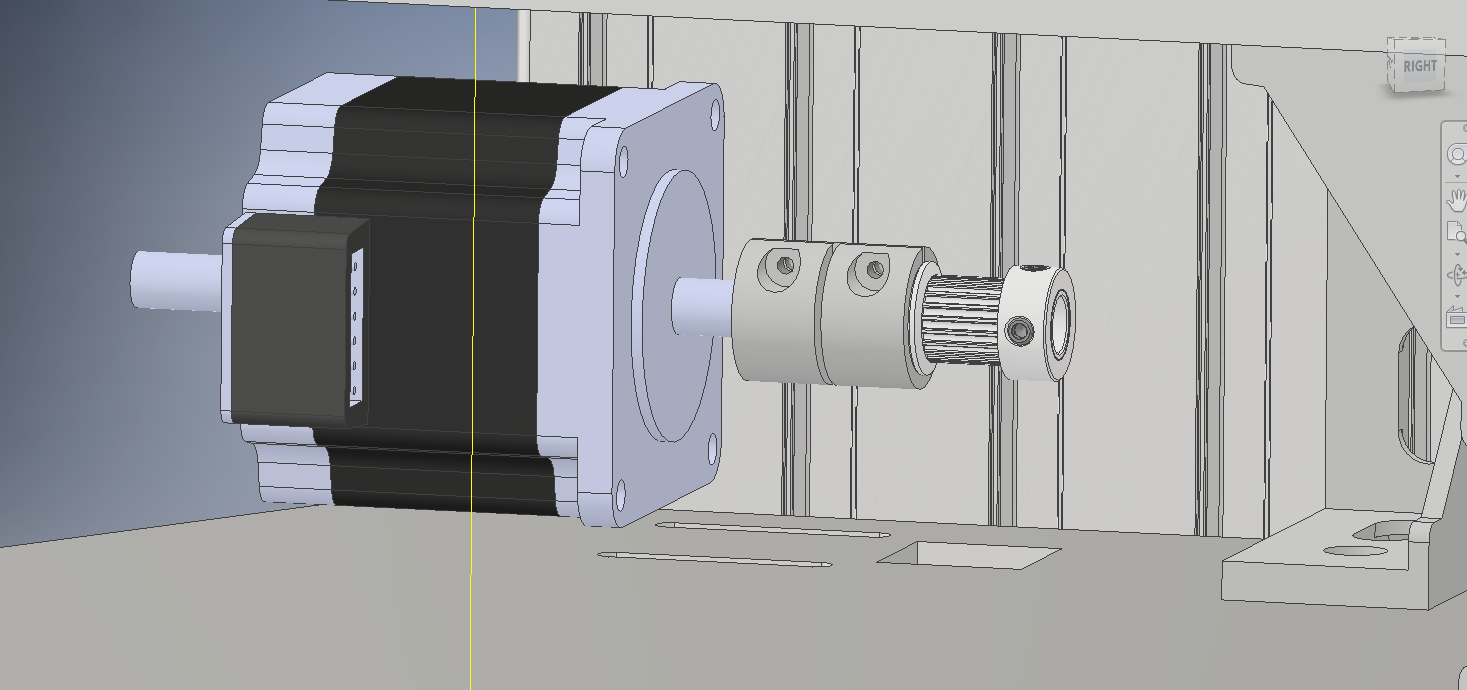
You are right. When I install the upgrades, that is how they will be mounted for sure. This is how the temporary model looks right now, excuse the lack of both bearings in the stackup, I forgot those when I was drawing it
 .
.
-
@dragonn said in External bearings for stepper shafts:
My solution, I know it is not perfect but works fine over hals a year. And before that I also broke my stepper motor shaft.Very nice! How wide is the part of the pulley that sits inside the bearing. With the pulleys I have at the moment, the contact surface would only be ~1mm wide.
-
@Nxt-1 yeah it is ~1mm, but if you can flip the pulley you get a nice, big contact surface.
For my application this is enough and it was the only way to fit it in without doing a major redesign to my printer. It is a heavy modified Hypercube Evolution, 10mm belt and gates pulley and roles. -
If you're breaking motor shafts or destroying motor bearings, you probably have the belt tension set too high.
If you're wearing out 3D printer idler pulleys with 3 mm or even 5 mm bore, I think it's to be expected. Compare the size of the bearings in those pulleys to the size of the bearings in the motor. The tiny balls in the bearings that are small enough to fit in those pulleys put a LOT of pressure on the races and wear either the races or the balls out. If you use stacked ball bearings for pulleys, you can use bearings with much larger diameter balls (like those in the motor) and get much longer operating life because the contact pressure is lower (same force from belt tension, but larger area of contact). They take up more space, but they typically don't cost much more than the 3D printer pulleys and they last a lot longer.
-
@mrehorstdmd gday could you share the stl file for this thank you terence
-
@terence Are you asking for the servo motor mount with the extra bearing? I used Fusion360 to design it specifically for the 45 mm t-slot I am using in the sand table. STL files are attached, but you might prefer the Fusion360 file so you can modify it easily to fit your t-slot...
The motor mounts are embedded in the sand table Fusion360 design file that you can DL here.
NEMA-17_servo_motor_mount_A.stl
NEMA-17_servo_motor_mount_B.stl
The motor mounts were designed using my "standard technique"- start with a model of the motor, pulley, bearing, and screws, add a solid block and carve away just enough plastic to fit the motors, belts, and other hardware. It results in a very chunky, solid mount that won't flex (much) under belt tension.
I did not end up using the extra bearing in the sand table motor mounts because one of the motors has a bit of runout in the shaft (I know, but how are you going to return it to China?) and it got pretty noisy with the extra bearing.