Three printers, poor consistency, questions
-
@luckyflyer It works on my E3D V6, so I suppose it does. It should work on pretty much any basic nozzle/block I would think.
-
Can you get a clearer image of that top layer? I can't decide if the gaps I see there have one or two (back and forth) lines of extrusion. If it's the latter, then you almost certainly have a mechanical backlash issue on an axis. I don't have any of those printers, but I have a few friends who do and they all has issues with slack belts and all had loose idlers on the x-axis. One also had a loose pulley on the motor shaft. I've also seen this effect reported by people who use steel reinforced belts. Any of this can of these cause backlash which manifests itself as a pattern of a double line then gap in top layers.
I don't use z-probes because I only ever use flat (on the scale of 3D printing) beds. I manually 3-point level the bed to the x/y plane and at the same time I set the z zero position... then I forget about it for a few months. As @Phaedrux said though, you should still be able to probe quite accurately with a BLTouch.
For the first time I had a mechanical endstop wear out last month - one day the trigger point was anywhere in a 200um range. I switched to an optical endstop as a replacement and can only say that I wish the other had died sooner.If you're unloading filament and seeing long wisps of fine material its 100% because the material is too hot when you're removing. Everyone has their own methods, the cold pull method will work every time, but that's time and effort and I'm lazy. My unload / material change scripts for PLA is to simply heat (or cool) to 100 deg.c and retract fast, then when I load I prime about 10 mm and that's enough for a clean change. For reference, that setup uses a standard E3D v6, BondTech BMG and ~350mm Bowden.
I also agree that your max volumetric flow rates seem pretty high. This can also be seen in your image where you're only seeing over-extrusion near the edges (assuming your acceleration settings aren't crazy). As the head is slowing down towards the end of the path and accelerating again the feedrate will be lower so the extrusion catches up.
How did you go about calibrating the VFR? If you're using a Bowden setup and don't extrude enough length when doing this calibration its easy to get max VFRs that are unrealistically high as the Bowden takes up the slack. -
Thanks for the responses guys. This forum is amazing. I always feel bad asked for help. A pet peeve of my wife. I just feel that answers are there if you just look. That being said, there are SOOOO many different answers that it started to frustrate me. I am working on some of the items that are mentioned here today and will reply back with my findings.
I thought it would be prudent to post my config.g file for review.
This is from my CR10S which is my oldest printer.
; Configuration file for Duet WiFi (firmware version 2.03) ; executed by the firmware on start-up ; ; generated by RepRapFirmware Configuration Tool v2.1.8 on Fri Apr 17 2020 15:50:42 GMT-0400 (Eastern Daylight Time) ; General preferences G90 ; send absolute coordinates... M83 ; ...but relative extruder moves M550 P"CR10S - 3DimensionGames" ; set printer name M564 H0 ; Network M552 S1 ; enable network M586 P0 S1 ; enable HTTP M586 P1 S0 ; disable FTP M586 P2 S0 ; disable Telnet ; Drives M569 P0 S0 ; Forwards M569 P1 S0 ; Forwards M569 P2 S1 ; Backwards M569 P3 S0 ; Forwards M584 X0 Y1 Z2 E3 ; set drive mapping M350 X16 Y16 Z16 E16 I1 ; configure microstepping with interpolation M92 X80.00 Y80.00 Z397.21 E408.00 ; set steps per mm M566 X960 Y960 Z30 E300.00 ; set maximum instantaneous speed changes (mm/min) M203 X12000.00 Y9600.00 Z600 E6000.00 ; set maximum speeds (mm/min) M201 X2500.00 Y2500.00 Z240.00 E5000.00 ; set accelerations (mm/s^2) M204 P500 T2500 ;distinguish between print and travel accel M906 X1000 Y1000 Z800 E1000 I50 ; set motor currents (mA) and motor idle factor in per cent M84 S30 ; Set idle timeout ; Axis Limits M208 X0 Y0 Z0 S1 ; set axis minima M208 X300 Y300 Z400 S0 ; set axis maxima ; Endstops M574 X1 Y1 S1 ; set active high endstops M574 Z1 S2 ; set endstops controlled by probe ; Z-Probe M307 H3 A-1 C-1 D-1 ; disable heater on PWM channel 3 for BLTouch M558 P9 H1.5 F60 T24000 ; set Z probe type to bltouch and the dive height + speeds G31 P500 X-41.8 Y-24 Z3.75 ; set Z probe trigger value, offset and trigger height M557 X15:255 S40 Y10:280 S45 ; define mesh grid ; Heaters M307 H0 B0 S1.00 ; disable bang-bang mode for the bed heater and set PWM limit M305 P0 T100000 B4092 R4700 ; set thermistor + ADC parameters for heater 0 M143 H0 S100 ; set temperature limit for heater 0 to 100C M305 P1 T100000 B4092 R4700 ; set thermistor + ADC parameters for heater 1 M143 H1 S275 ; set temperature limit for heater 1 to 275C ; Fans M106 P0 S0 I0 F500 H-1 ; set fan 0 value, PWM signal inversion and frequency. Thermostatic control is turned off M106 P1 S1 I0 F500 H1 T45 ; set fan 1 value, PWM signal inversion and frequency. Thermostatic control is turned on M106 P2 S1 I0 F500 H1 T45 ; set fan 2 value, PWM signal inversion and frequency. Thermostatic control is turned on ; Tools M563 P0 D0 H1 F0 ; define tool 0 G10 P0 X0 Y0 Z0 ; set tool 0 axis offsets G10 P0 R0 S0 ; set initial tool 0 active and standby temperatures to 0C ; Custom settings are not configured M501 ;M572 D0 S0.25; set K-factor -
I might increase the E jerk a little bit. Are you using pressure advance?
-
I have the line of code uncommented at the bottom, but wanted to leave it off until I solve my issues. I didn't want to introduce another variable.
-
@ChrisP said in Three printers, poor consistency, questions:
Can you get a clearer image of that top layer? I can't decide if the gaps I see there have one or two (back and forth) lines of extrusion. If it's the latter, then you almost certainly have a mechanical backlash issue on an axis. I don't have any of those printers, but I have a few friends who do and they all has issues with slack belts and all had loose idlers on the x-axis. One also had a loose pulley on the motor shaft. I've also seen this effect reported by people who use steel reinforced belts. Any of this can of these cause backlash which manifests itself as a pattern of a double line then gap in top layers.
I don't use z-probes because I only ever use flat (on the scale of 3D printing) beds. I manually 3-point level the bed to the x/y plane and at the same time I set the z zero position... then I forget about it for a few months. As @Phaedrux said though, you should still be able to probe quite accurately with a BLTouch.
For the first time I had a mechanical endstop wear out last month - one day the trigger point was anywhere in a 200um range. I switched to an optical endstop as a replacement and can only say that I wish the other had died sooner.If you're unloading filament and seeing long wisps of fine material its 100% because the material is too hot when you're removing. Everyone has their own methods, the cold pull method will work every time, but that's time and effort and I'm lazy. My unload / material change scripts for PLA is to simply heat (or cool) to 100 deg.c and retract fast, then when I load I prime about 10 mm and that's enough for a clean change. For reference, that setup uses a standard E3D v6, BondTech BMG and ~350mm Bowden.
I also agree that your max volumetric flow rates seem pretty high. This can also be seen in your image where you're only seeing over-extrusion near the edges (assuming your acceleration settings aren't crazy). As the head is slowing down towards the end of the path and accelerating again the feedrate will be lower so the extrusion catches up.
How did you go about calibrating the VFR? If you're using a Bowden setup and don't extrude enough length when doing this calibration its easy to get max VFRs that are unrealistically high as the Bowden takes up the slack.Hi Chris,
I grabbed my camera and searched for a worst case picture of the issue above. Luckily it was white filament and give contrast on the gaps.
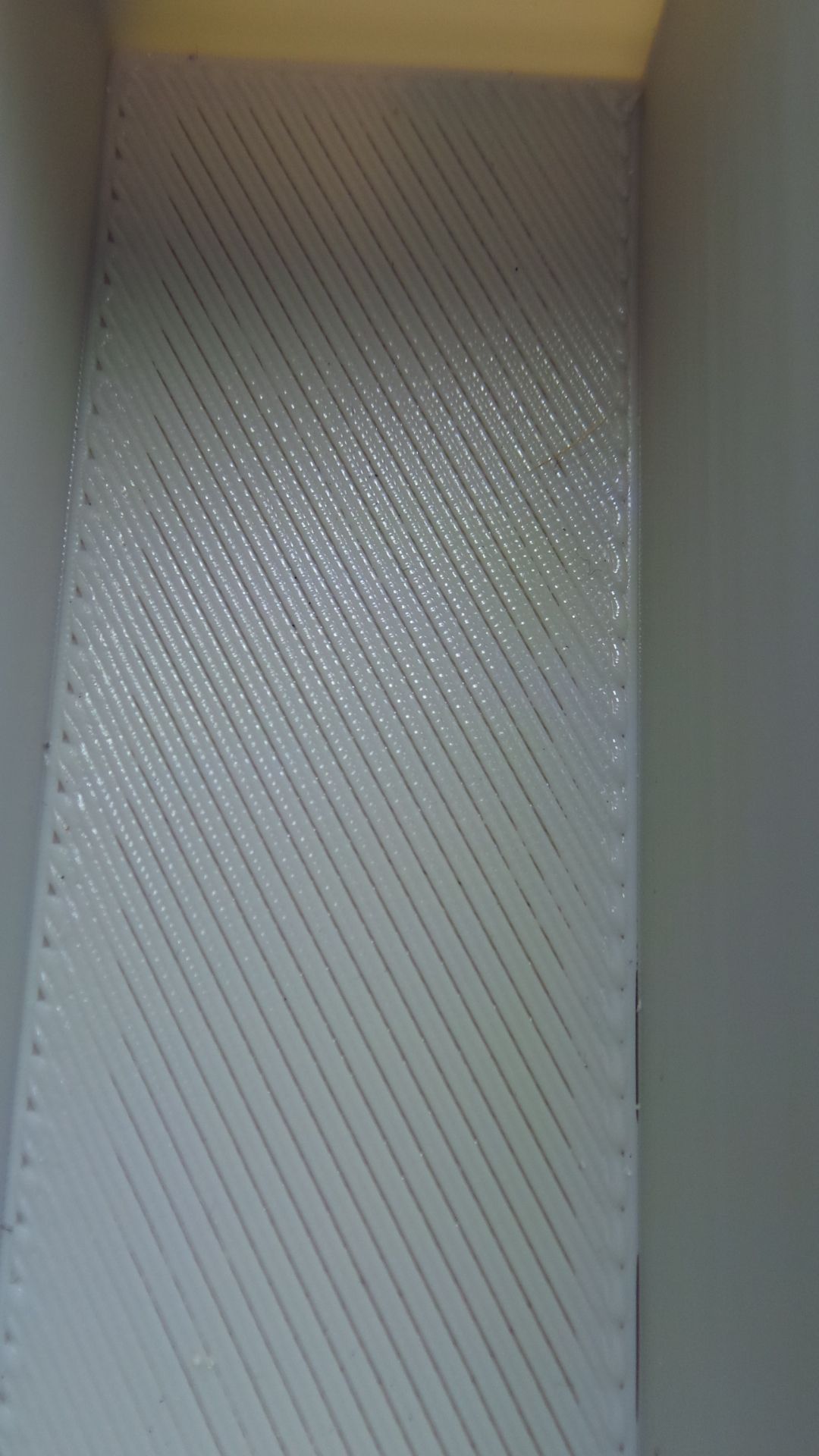
Its quite clear that it is 2 lines and a space repeated. So I will check into what you have described. The pain is, there is no infill space below this. Its between 4 and 8 solid layers making the bottom of an box. So the common answer I always get is increase the number of top layers. They are technically all top layers...or all bottom laters. I have been able to mask it by decreasing my top skin speed to a much slower speed. But that is not the fix I am looking for.
Regarding the VFR, I followed a calibration guide on here. But it simply talks about the extruder skipping. But what I noticed over the weekend when calibrating my Ender 5 Plus, is the bowden tube moves at a certain point, much sooner than when the extruder skips. So I will be paying attention to that bowden tube movement and use that as a guide that the pressure is getting high to back up the filament.
Thanks
Ryan -
The bowden clips on the Creality printers are pretty poor. Same with the PTFE tubing. They tend to wear and get looser over time which can lead to some odd retraction behaviours. There are plenty of upgrade kits and replacement options.
There are also belt tensioner options that could help a lot with X Y belt backlash.
Both would be worthwhile attempts at fixes for the issue shown.
-
@RyanP said in Three printers, poor consistency, questions:
Its quite clear that it is 2 lines and a space repeated. So I will check into what you have described. The pain is, there is no infill space below this. Its between 4 and 8 solid layers making the bottom of an box. So the common answer I always get is increase the number of top layers. They are technically all top layers...or all bottom laters. I have been able to mask it by decreasing my top skin speed to a much slower speed. But that is not the fix I am looking for.
Yeh, if you can't get an even, gap-less layer on the first layer(s), then adding more isn't going to help. Fixing the root of the problem will likely involve a little though, effort & time, but you'll thank yourself for it later.
If you re-print that part and watch not which direction the head is travelling relative to the gaps/overlap, its actually possible to figure out which axis has the issue. Sometimes is easier to figure out by printing a small test part (just a few layers) that has an internal hole as the perimeters will look slightly elliptical oftem with small flats. The axis that runs perpendicular to the flat is the one with the problem.If there are flats in both directions then both axis have an issue.Regarding the VFR, I followed a calibration guide on here. But it simply talks about the extruder skipping. But what I noticed over the weekend when calibrating my Ender 5 Plus, is the bowden tube moves at a certain point, much sooner than when the extruder skips. So I will be paying attention to that bowden tube movement and use that as a guide that the pressure is getting high to back up the filament.
@Phaedrux's comments about Bowden clips matches what I've heard from others. One thing that also often missed with any Bowden setup is to put the retaining clip on but then to give the tube another shove in while the collar is held up. It's often surprising how much further you can push it in... note that it can make it a bit of a pig to push the collar down if you want to remove the tube as it'll have practically no travel.
I'm absolutely not a fan of the skipping extruder method, particularly if you have a decent dual drive geared extruder like a BondTech as you'll probably grind filament before you notice skipping. Tuning for max VFR is not a thing I often do on desktop-scale printers as I aim for absolute precision than speed at that scale. However, the way I've found to be most consistent is to actually just print a series of test parts. Draw up a cuboid that has some decent length edges, but is fairly short so it doesn't take long, say 50x50x5 mm. The key thing is to make sure the lengths are long enough to make sure your Bowden tube isn't still taking up slack.
Slice it in vase mode with no top, bottom or infill and print one at a sensible, steady speed and temperature. I use 40 mm/s or so for a standard 0.4 nozzle using 1.2 x nozzle size or greater for extrusion width and 0.15 or 0.20 mm layers... so ~3 mm^3/s. For your 1 mm nozzle volcano setup I'd probably start with 0.3 mm layers, 1.2 mm extrusion width and 30 mm/s speed (~11 mm^3/s). Print it and measure the wall thickness - if it's not whatever you set your extrusion width was set to then you'll want to sort that first.
Repeat printing this with increasing speeds until you the wall thickness drops below what you'd consider an acceptable deviation. To reduce the number of prints, you could try a simple binary search methodology. Don't forget though that the faster you print, the faster you'll need to get energy into the filament so at some point you'll have to decide whether you want to find the max VFR for your standard temperature or whether you're wanting to explore increasing temperatures to push the VRF up. Based on what you've said so far, I'd probably save increasing temps for another day once you have some nicely tuned profiles.
-
@ChrisP said in Three printers, poor consistency, questions:
Don't forget though that the faster you print, the faster you'll need to get energy into the filament so at some point you'll have to decide whether you want to find the max VFR for your standard temperature or whether you're wanting to explore increasing temperatures to push the VRF up. Based on what you've said so far, I'd probably save increasing temps for another day once you have some nicely tuned profiles.
I'll reply to the sections before this in another post as the VRF aspect is important for the speed I am trying to determine I can print at.
Since I wasn't able to find any details beyond the "skipping" method, and figured I'd look at it and see how it can be modified to assist with bowden tube setups.
So the dozuki ender 3 guide suggests 50mm and increasing by 1mm/s. I'm assuming its being done with a 0.4 nozzle, and I'm using a 0.6 nozzle. But I did two things different.
One, I doubled the length in the guide. So instead of 50mm followed by 100mm. I started with 100mm, and verified with 200mm. The extra constant length over 50 gives more time for pressure to build up.And two, I paid close attention to the bowden tube and its movements. Especially when the extrusion finishes. Anything more than slight flex, I lowered my feed rate.
- heat nozzle to 220c
- turn on part cooling fan to 20% (I may change this after some test prints)
- extrude 100mm @5mm
- increase by 1mm/s until poor bowden movement or skipping
(both which seemed to happen at 10mm/s) - Decreased to 9mm/s, extrude 100, no skipping, but the flex was still there
- Double to extrude to 200mm @ 9mm/s (poor flex and skip)
- Stayed with 200mm but dropped to 8mm/s, nominal flex and no skipping
So based on that, I am going to use 8mm/s as the feed rate.
Max Flow Rate = Max Input Feed rate * pi * (Filament Diameter/2)2
MFR = 8mm/s * pi * (1.72/2)2 (I used 1.72 as I often get that result in filament measurement)
MFR = 18.5 or 18.
I'm going to test this and see how things change.
-
You may find this excel sheet useful: https://www.dropbox.com/s/ihe3rl58z7sdyfu/Calculators.xlsx?dl=0
Your method sounds good. And yes the Ender guide is using a 0.4 nozzle, though it's irrelevant to the calculation since it's already built into the system. It's also only one test to give you a reasonable limit to try and stay within for your speed/flow rate combos. Verify with actual prints. If you're doing large objects with lots of solid infill you're going to cool the hotend more quickly than if you were printing small detail models with lots of short moves.
It's also informative to run the test again at a few different temperatures.
Doubling the length to 200mm makes sense if you're printing those large object with lots of area to fill, but less so or much smaller objects, so testing with 50mm is also useful.