Tool board configuration
-
Evening all. I hooked up my tool board this evening to update the firmware. After some fiddling with the can bus wiring, I got it to update. Then I started working on my config.g to read the sensors from the tool board. This is where I am having some troubles.
I was using examples from https://miscsolutions.wordpress.com/2020/03/04/converting-the-e3d-tool-changer-to-duet-3-with-hemera-tools-part-2/
This is my config.g file currently. I have left the default can bus address of 121 set.
; Configuration file for Duet 3 (firmware version 3)
; executed by the firmware on start-up
;
; generated by RepRapFirmware Configuration Tool v2.1.8 on Sun Apr 05 2020 04:11:56 GMT-0400 (Eastern Daylight Time)

; General preferences
G90                                          ; send absolute coordinates...
M83                                          ; ...but relative extruder moves
M550 P"Duet 3"                               ; set printer name

; Drives
M569 P0.0 S1                                 ; physical drive 0.0 goes forwards
M569 P0.1 S1                                 ; physical drive 0.1 goes forwards
M569 P0.2 S1                                 ; physical drive 0.2 goes forwards
M569 P121.0 S1                                 ; physical drive 0.3 goes forwards
M584 X0.0 Y0.1 Z0.2 E121.0                     ; set drive mapping
M350 X16 Y16 Z16 E16 I1                      ; configure microstepping with interpolation
M92 X80.00 Y80.00 Z4000.00 E420.00           ; set steps per mm
M566 X900.00 Y900.00 Z12.00 E120.00          ; set maximum instantaneous speed changes (mm/min)
M203 X6000.00 Y6000.00 Z180.00 E1200.00      ; set maximum speeds (mm/min)
M201 X500.00 Y500.00 Z20.00 E250.00          ; set accelerations (mm/s^2)
M906 X1200 Y800 Z1500 E750 I30                 ; set motor currents (mA) and motor idle factor in per cent
M84 S30                                      ; Set idle timeout

; Axis Limits
M208 X0 Y0 Z0 S1                             ; set axis minima
M208 X690 Y330 Z400 S0                       ; set axis maxima

; Endstops
M574 X1 S0 P"io0.in"                         ; configure active-low endstop for low end on X via pin io0.in
M574 Y1 S0 P"io1.in"                         ; configure active-low endstop for low end on Y via pin io1.in
M574 Z1 S0 P"io2.in"                         ; configure active-low endstop for low end on Z via pin io2.in

; Z-Probe
M558 P0 H5 F120 T6000                        ; disable Z probe but set dive height, probe speed and travel speed
M557 X15:215 Y15:195 S20                     ; define mesh grid

; Heaters
M308 S0 P"temp0" Y"thermistor" T100000 B4138 ; configure sensor 0 as thermistor on pin temp0
M950 H0 C"out0" T0                           ; create bed heater output on out0 and map it to sensor 0
M143 H0 S120                                 ; set temperature limit for heater 0 to 120C
M307 H0 B1 S1.00                             ; enable bang-bang mode for the bed heater and set PWM limit
M140 H0                                      ; map heated bed to heater 0
M308 S1 P"121.temp1" Y"thermistor" T100000 B4138 ; configure sensor 1 as thermistor on pin temp1
M950 H1 C"121.out0" T1                           ; create nozzle heater output on out1 and map it to sensor 1
M143 H1 S280                                 ; set temperature limit for heater 1 to 280C
M307 H1 B0 S1.00                             ; disable bang-bang mode for heater  and set PWM limit

; Fans
M950 F0 C"121.out1" Q500                         ; create fan 0 on pin out3 and set its frequency
M106 P0 S0 H-1                               ; set fan 0 value. Thermostatic control is turned off
M950 F1 C"121.out2" Q500                         ; create fan 1 on pin out4 and set its frequency
M106 P1 S1 H1 T45                            ; set fan 1 value. Thermostatic control is turned on

; Tools
M563 P0 D0 H1 F0                             ; define tool 0
G10 P0 X0 Y0 Z0                              ; set tool 0 axis offsets
G10 P0 R0 S0                                 ; set initial tool 0 active and standby temperatures to 0C

; Custom settings are not defined

; Miscellaneous
M501                                         ; load saved parameters from non-volatile memory
As you can see, my extruder temp is still showing nothing. Any ideas to remedy this?

Thank you. Also, all firmwares are up to date.
-
This works for me, my tool board is CAN 22. I also have tools on a 3HC at CAN 1.
; Temperature sensors
M308 S0 P"0.temp0" Y"thermistor" T100000 B3950 A"Bed"
M308 S1 P"1.temp0" Y"thermistor" T100000 B3950 A"HE1"
M308 S2 P"1.temp1" Y"thermistor" T100000 B3950 A"HE2"
M308 S3 P"22.temp0" Y"thermistor" T100000 B3950 A"HE3"
;M308 S4 P"23.temp0" Y"thermistor" T100000 B3950 A"HE4"

; Heaters
M950 H0 C"0.out0" T0           ; Bed.  H = Heater 0, C is output for heater itself, T = Temperature sensor (defined above)
M950 H1 C"1.out0" T1           ; Heater for extruder out tool 0
M950 H2 C"1.out1" T2           ; Heater for extruder out tool 1
M950 H3 C"22.out0" T3           ; Heater for extruder out tool 2
;M950 H4 C"23.out0" T4           ; Heater for extruder out tool 3

; Further setup for bed
M143 H0 S130                                           ; set temperature limit for heater 0 to 130C
M307 H0 B0 S1.00                                       ; disable bang-bang mode for the bed heater and set PWM limit
M140 H0                                                ; map heated bed to heater 0

; Default heater model
;;;;M307 H0 A270.7 C90.4 D6.7 B0 S1.0          ; Default Bed Heater Parameters, before tuning / if config-override.g is missing
; Calibration 28 Oct 2019
;Heater 0 model: gain 139.6, time constant 252.2, dead time 0.7, max PWM 1.00, calibration voltage 24.5, mode PID
;Computed PID parameters for setpoint change: P468.8, I35.594,  D225.7
;Computed PID parameters for     load change: P468.8, I136.631, D225.7
M307 H0 A140 C252 D0.7 S1.0 V24.5 B0       ; Tuned Bed Heater Paramaters, same as report above, also B0 to turn off bang-bang

; Fans for hot end cooling
M950 F1 C"1.out6"
M106 P1 S255 H1 T45    ; S = Speed of fan Px, Hxx = heater for thermo mode, T = temps for thermo mode.
M950 F2 C"1.out7"
M106 P2 S255 H2 T45    ; S = Speed of fan Px, Hxx = heater for thermo mode, T = temps for thermo mode.
M950 F3 C"22.out1"
M106 P3 S255 H3 T45    ; S = Speed of fan Px, Hxx = heater for thermo mode, T = temps for thermo mode.
;M950 F4 C"23.out1"
;M106 P4 S255 H4 T45    ; S = Speed of fan Px, Hxx = heater for thermo mode, T = temps for thermo mode.

; Fans for print cooling
M950 F5 C"1.out3"
M106 P5 C"PrintCool5"
M950 F6 C"1.out4"
M106 P6 C"PrintCool6"
M950 F7 C"22.out2"
M106 P7 C"PrintCool7"
;M950 F8 C"23.out2"
;M106 P8 C"PrintCool8"

; Tool definitions
M563 P0 S"Tool 0" D0 H1 F5      ; Px = Tool number, Dx = Drive Number (start at 0, after movement drives), H1 = Heater Number, Fx = Fan number print cooling fan
G10  P0 S0 R0                   ; Set tool 0 operating and standby temperatures(-273 = "off")
;M572 D0 S0.1  		            ; Set pressure advance on

M563 P1 S"Tool 1" D1 H2 F6      ; Px = Tool number, Dx = Drive Number (start at 0, after movement drives), H1 = Heater Number, Fx = Fan number print cooling fan
G10  P1 S0 R0                   ; Set tool 0 operating and standby temperatures(-273 = "off")
;M572 D1 S0.1		            ; Set pressure advance on

M563 P2 S"Tool 2" D2 H3 F7      ; Px = Tool number, Dx = Drive Number (start at 0, after movement drives), H1 = Heater Number, Fx = Fan number print cooling fan
G10  P2 S0 R0                   ; Set tool 0 operating and standby temperatures(-273 = "off")
;M572 D2 S0.1		            ; Set pressure advance on

;M563 P3 S"Tool 3" D3 H4 F8      ; Px = Tool number, Dx = Drive Number (start at 0, after movement drives), H1 = Heater Number, Fx = Fan number print cooling fan
;G10  P3 S0 R0                   ; Set tool 0 operating and standby temperatures(-273 = "off")
;;M572 D3 S0.1		            ; Set pressure advance on
Delta / Kossel printer fanatic
-
Please try the following:
- Check whether the config settings have been applied, by sending M308 S1 and M950 H1 and checking the response.
- Run M98 P"config.g" and see if any errors are reported.
@madmattco said in Tool board configuration:
Also, all firmwares are up to date.
Please specify the firmware versions. Your idea of up to fate might not be the same as ours!
Duet WiFi hardware designer and firmware engineer
Please do not ask me for Duet support via PM or email, use the forum
http://www.escher3d.com, https://miscsolutions.wordpress.com -
@dc42 I am using the firmware you posted the other day. https://github.com/dc42/RepRapFirmware/releases/tag/3.01-RC12
My problem ended up being the wrong temp sensor connector.

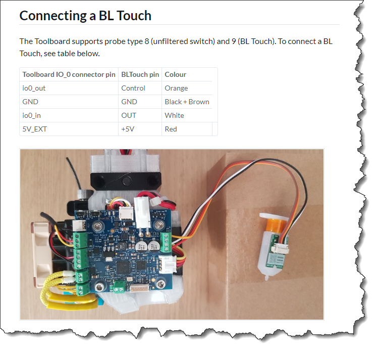
I was also wondering if everything is in place to have a bl-touch running off of the IO_0 port on the tool board.
-
@madmattco said in Tool board configuration:
My problem ended up being the wrong temp sensor connector.
I'm glad you solved it.
I was also wondering if everything is in place to have a bl-touch running off of the IO_0 port on the tool board.
Yes.
Duet WiFi hardware designer and firmware engineer
Please do not ask me for Duet support via PM or email, use the forum
http://www.escher3d.com, https://miscsolutions.wordpress.com -
@dc42 Cheers
-
@Danal You wouldnt happen to have a bl-touch on your toolboard would you?
-
@madmattco said in Tool board configuration:
@Danal You wouldnt happen to have a bl-touch on your toolboard would you?
Not on the toolboard. I do have a BLt, it is on io4 on the mainboard.
Here is the setup. Unless the firmware does/doesn't support something, I don't see why this couldn't be xx.io0.in (and out) on a toolboard.
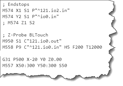
M558 K0 P9 C"^io4.in" H9 A5 T6000 S0.02 ; Z probe BLtouch - Set the height of the bed when homing G28. Combined with content of bed.g as invoked by G32, levels bed. Also used for Mesh. ; Hn = dive height ; A bigger dive height prevents a situation where the bed is out of alignment by more than the dive height ; on any corner, which can crash the hot-end into the bed while moving the head in XY. ; Probing speed and travel speed are similarly reduced in case the Z probe isn't connected properly (or ; disconnects later after moving to a point) giving the user more time to stop. ; An = Number of times to probe each point. ; Tnnn = Travel speed between probe points. ; Snnn = Tolerance when probing multiple times. Two readings inside this window and we move on. G31 K0 X28.1 Y-27.5 Z0 ; Probe offsets M950 S0 C"^io4.out" ; Servo Control Pin for BLtouch. -
@Danal That worked for me sir. Cheers
-
I have a BLTouch on my toolboard, if you need some help.
-
@Nuramori Care to share your BLTouch config on Toolboard? I've tried setting it up using the RRF configurator, but I can't pick ioO.out as PWM for BLTouch, when also using Out 0 for heater.. don't know if there is a shared PWM (hope not) or just bad RRF configurator?
RepRapFirmware supported G-codes: https://duet3d.com/wiki/G-code
-
I’m happy to, but I won’t be able to get to it until I’m back from vacation. Sunday is the likely opportunity.
-
@Nuramori I got it working.. sort of. !! (Original BLTouch v3.1 on Toolboard v1) All newest firmware (non-rc).
- It does not selftest on power on of machine.
- If I unplug BLTouch, power machine on, and plug in BLTouch after machine has started it does self test.
- I've done a lot of continuity tests, and all wires are connectors are good all around.
- I've measured on the connectors on Toolboard which reads 5v.. but when connecting BLTouch it briefly drops below 3v, so my issues might be some voltage drop?
- Once the machine is ready I can run a long self test. It will however blink red afterwards, and I can't do a new self test.
- The "reset warning and retract probe" does not work in this case.. but if I deploy and retract it stops blinking and I can do a new self test, and it starts over.
- I can get it to use the "reset warning SW mode".. but can't do anything afterwards.
- Z probe reads as 0. When I deploy and manually trigger it, it reads 1000 as it should
- I noticed it is VERY weak, compared to other machine's BLTouch (maybe voltage issue?)
- I've considered issuing the EEProm command to put it into 5v state, but I'm unsure wheter I risk burning something?
Sidenote: I'm using a Quality Meanwell HRP psu. I measure output Volt at 24.2 at PSU and on Duet3 terminals,, while Duet3 reports it at 23.7v. Always... I find this somewhat.. odd? Using a decent quality Multiemter.
RepRapFirmware supported G-codes: https://duet3d.com/wiki/G-code
-
@dintid said in Tool board configuration:
I've measured on the connectors on Toolboard which reads 5v.. but when connecting BLTouch it briefly drops below 3v, so my issues might be some voltage drop?
You could try adding a 100uF capacitor between the BLTouch +5V and ground connections.
Sidenote: I'm using a Quality Meanwell HRP psu. I measure output Volt at 24.2 at PSU and on Duet3 terminals,, while Duet3 reports it at 23.7v. Always... I find this somewhat.. odd? Using a decent quality Multiemter.
The Duet uses its 3.3V regulator as the voltage reference, so it can be few percent inaccurate. Your multimeter is probably more accurate.
Duet WiFi hardware designer and firmware engineer
Please do not ask me for Duet support via PM or email, use the forum
http://www.escher3d.com, https://miscsolutions.wordpress.com -
Out of curiosity, do you have a terminating resistor on your can-fd line?
-
@Nuramori I don't know what that means? I have the requisite jumpers on my Distribution board.
-
@dc42 I only had a 35v 470uf. It didn't make a difference.
In your documentation you write that Orange i control wire.. but it's really yellow though?
https://duet3d.dozuki.com/Wiki/Duet_3_Tool_Board#Section_Connecting_a_BL_Touch
RepRapFirmware supported G-codes: https://duet3d.com/wiki/G-code
-
@dintid said in Tool board configuration:
In your documentation you write that Orange i control wire.. but it's really yellow though?
It depends on your colour vision and how you assign colours. I see it as orange.
Duet WiFi hardware designer and firmware engineer
Please do not ask me for Duet support via PM or email, use the forum
http://www.escher3d.com, https://miscsolutions.wordpress.com -
@dc42 I'm colorblind but asked my two girls who aren't
")
Any ideas to steps I can try to make BLTouch work on the Toolboard? I havn't had time to try it on the mainboard yet.RepRapFirmware supported G-codes: https://duet3d.com/wiki/G-code
-
@dintid said in Tool board configuration:
@dc42 I'm colorblind but asked my two girls who aren't
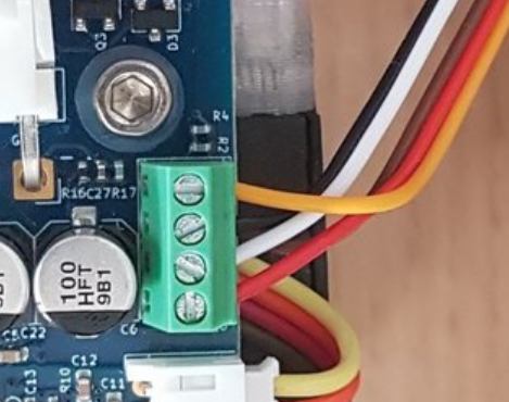
Any ideas to steps I can try to make BLTouch work on the Toolboard? I havn't had time to try it on the mainboard yet.It's odd that it's not working, because BLTouch worked fine connected to the tool board when I took that photo. Are you certain that you have connected the wires correctly? The brown wire goes to ground (2nd terminal from the top) along with the black wire, which isn't clear in that photo.