Choosing a Z axis style
-
Hello everyone,
I found that I have too much time on my hands, and decided to design and build a 3D printer myself
") . Not because there aren't any good ones to buy, but to learn something and have fun doing so.
. Not because there aren't any good ones to buy, but to learn something and have fun doing so.Details most relevant to this post:
- Heated chamber (around 70 °C)
- Print bed heatable up to 150 °C
- Print bed size: around 30cm x 30cm
- Frame built from aluminum extrusions (2020, 2040 or 4040; not sure yet)
- Most parts will be 3D printed (including the bed mounts). Yes, I know, PLA will not work in a heated chamber
")
- And of course: driven by a Duet board!
I did some research and looked around how other printers handle their print bed / Z axis, and came up with three alternatives that I like:
-
A single linear guide to restrict movement of the bed to strictly up/down, and three lead screws for lifting it:
-
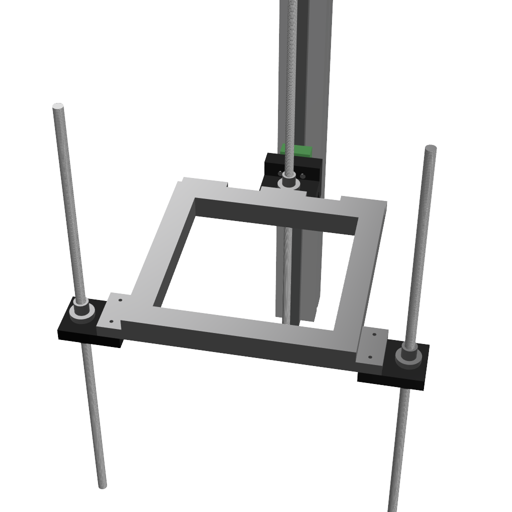
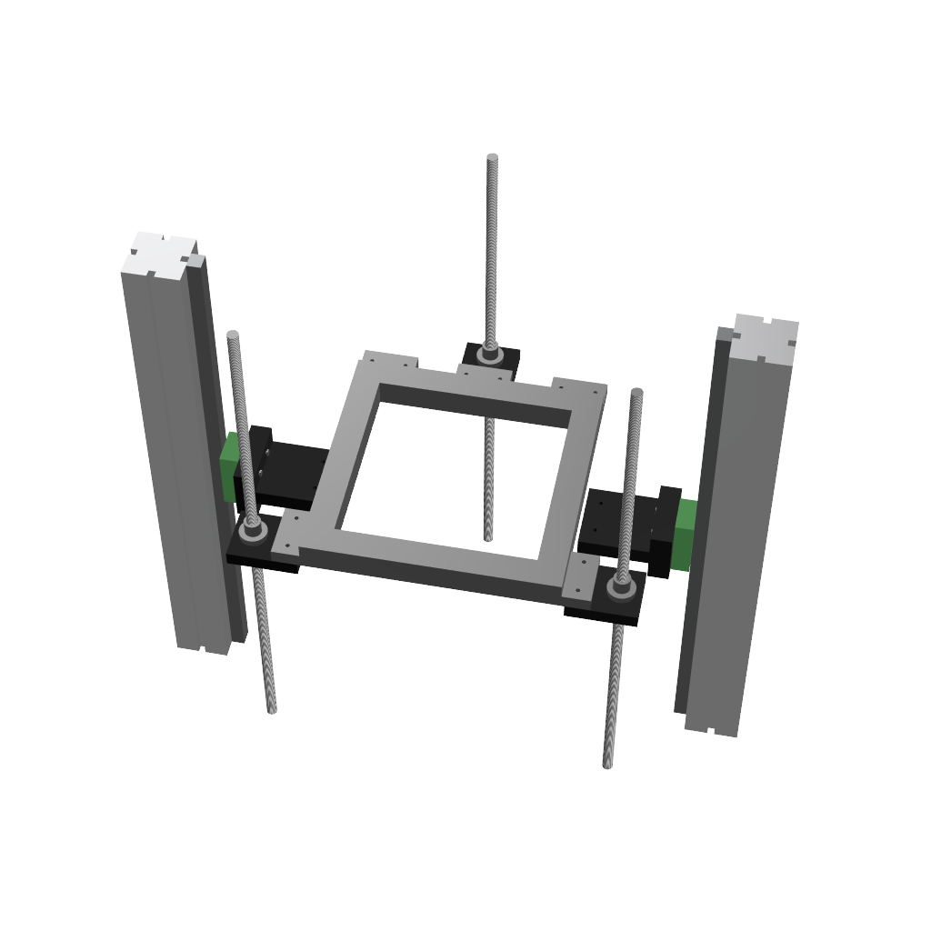
Similar to option 1, but with two linear guides:
-
A kinematic mount with three linear guides, each with a lead screw for lifting. This is the mechanism used by the Jubilee printer:
(The bed frame is shown as 'levitating'; in reality, it would sit on the dowel pins.)
(Models are just quick-and-dirty, with little details. Also, print bed is not shown (just the frame); bed will probably be mounted on the frame using a kinematic mount as described here:
https://drmrehorst.blogspot.com/2017/07/ultra-megamax-dominator-3d-printer-bed.html)Now I'm trying to decide which of these options I like most. Here are my thoughts:
- Single linear guides:
- Pro: cheapest solution; easiest to align.
- Con: might not have enough resistance against rotation around Z axis (but not sure; I have no experience with linear guides)
- Unsure: what about thermal expansion? If the bed frame expands differently than the main frame, will the lead screws be bent a little bit to "make room"? Is this a problem?
- Two linear guides:
- Pros: better resistance against Z-rotation
- Cons: harder to align, as the two linear guides must be perfectly parallel
- Unsure: If the bed frame expands differently than the main frame, that might cause problems at the bed/slide mounts.
- Jubilee's kinematic mount:
- Pro: Absolutely no problems with thermal expansion. The bed (or in my example: the bed frame) can just slide on the dowel pins when it expands or contracts.
- Cons: most expensive solution.
- Unsure: alignment! It seems quite hard to me to get them perfectly aligned. If they aren't, the bed will rotate around the Z axis when it's lifted/lowered. Or do I miss something?
So far, I like option 2 (two linear guides) best. However, I'm nost sure about thermal expansion. Let's assume I build bed frame and main frame from the same material. Then the distance between the two linear guides should grow by the same amount as the bed frame. The same should be true for the distance between the front lead screws and the back lead screw. If not, the lead screws will get bent a tiny bit (probably not relevant for print quality), so nothing should bind.
I would be glad for any thoughts and opinions.
-
@RS In the first option, the distance between the two front screws and the linear guide is a long lever arm. If the the screws aren't perfectly straight, they may be able to twist the guide rail/t-slot at the back enough to cause print quality issues.
In option 2, that is unlikely to be a problem, but it's generally a good idea to keep screws as close to linear guides as possible, so I'd put the linear guides close to the to front screws instead of at the back.
The third one could work well, but aligning 3 linear guides might be a problem, and keeping them aligned as the frame expands when heated could also be an issue.
-
I wetn whit something more simple for my custom build , the problem with multiple leadscrew is if one motor is not perfectly in cadence with the other your bed will not be level , my hole bed platform is resting on 2 linear guide with 2 roller block on each side

-
Hi,
I've tried a few different arrangements over the years.
My current build has one set of two 12mm guide rods and one 8mm lead screw (2mm lead) on the left side and another set on the right side.
The lead screws are belt driven by one stepper. The Z drive parts are not shown in this image.
Frederick
-
Thanks for all the answers so far. There are so many ways to do basically the same thing: lift the bed up and down
What I'm quite sure about is that I want to avoid guide rods, and use linear guides instead. It seems those tend to be more precise than rods, and I've got the budget for linear guides. But I think many considerations are the same, no matter if rods or guides.
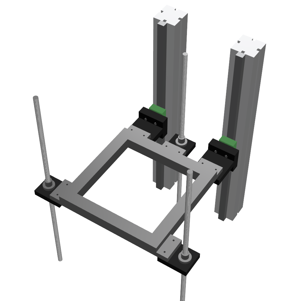
@mrehorstdmd: Yeah, that lever is troublesome, now that I think about it. Moving the guides more towards the front results in a more balanced structure. Here's a mock-up of that change:
I think I'll place the guides roughly 1/3 of the way from front to back.What I'm not sure about yet, and maybe someone else got some experience with, is what happens when the printer heats up. Assuming the printer has a width of 50cm and is built of aluminum, when heated up from 20 °C to 70 °C it will expand by 500mm * 50 °C * 24*10^-6/°C = 0.6mm. That would cause quite some pull on the bed frame from the left and right.
However, the bed frame will also expand. Would it be safe to assume that it will expand similary enough to the main frame, and thus not cause issues?If that's not a safe assumption, one of the two slide mounts would have to be replaced with something more flexible. The same would apply to the lead screw mount. I'll mock something up in Fusion and post it a bit later today.
-
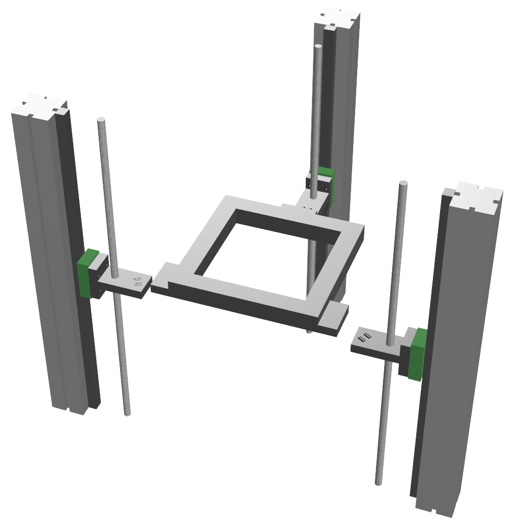
So here's a quick mock-up of the kind of flexible mount I was thinking about:
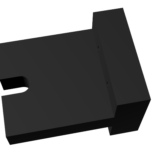
One of the two mounts on the slides would stay unchanged; let's say the left one. Then the right one would be replaced by this flexible mount. This would allow the print frame's right side to move in the X direction, while not allowing any flexibility in the Y directions.
I would also replace the lead screw mounts with this. The lead screws only need to restrict Z; with the slot in the mount, they wouldn't be able to interfere with X and Y movements.
Does this make sense? Or is this just massive overkill?
-
In my printer, the frame and bed support are all made of 4040 t-slot. I made the assumption that they'd heat up together and it seems to be working fine without any special gizmos to allow differential expansion. The bed is on a kinematic mount that allows it to expand more and separately from the much cooler bed support. If you are worried about it, one of the bed supports could also be on a sliding kinematic mount.
-
If it's working for you, @mrehorstdmd, then I'll start with that as well. Should it ever cause problems, then I can still replace it with a more fancy mount.
The bed itself will definitely need a kinematic mount. I also plan to add thermal decoupling using PTFE blocks, just to be sure that the bed won't heat the bed frame to a point where it will melt its mounts.
-
One more thought/question: should the lead screws be fixed only at the bottom (or top?), or on both ends? I think only fixing one end would be better (don't want them overconstrained), but I'm not sure.
-
@RS said in Choosing a Z axis style:
but I'm not sure.
You can be sure now. Overconstraint is bad. For the loads and sizes we're using in printers it's best to leave one end free to prevent any curve in the screw to be transferred to the bed platform as an XY shift.
-
@RS said in Choosing a Z axis style:
What I'm quite sure about is that I want to avoid guide rods, and use linear guides instead. It seems those tend to be more precise than rods, and I've got the budget for linear guides.
Linear guides are fine.
I've used both rods and guides and have found no noticeable difference in the finished printed products.
Good luck.
Frederick
-
@Phaedrux said in Choosing a Z axis style:
You can be sure now. Overconstraint is bad. For the loads and sizes we're using in printers it's best to leave one end free to prevent any curve in the screw to be transferred to the bed platform as an XY shift.
Ok, thanks for confirming this. Then I'll leave one end "floating".
I wonder if it matters whether they are fixed at the top or the bottom. But most likely, I'll mount them at the bottom, as that's easier.@fcwilt said in Choosing a Z axis style:
Linear guides are fine.
I've used both rods and guides and have found no noticeable difference in the finished printed products.
That's interesting, as I've read alot about bad print quality due to rods. Where those high-precision rods, or the standard, cheap stuff that's found in budget printers?
-
@RS said in Choosing a Z axis style:
I wonder if it matters whether they are fixed at the top or the bottom. But most likely, I'll mount them at the bottom, as that's easier.
It's easier to carry the weight on a thrust bearing at the bottom than dangle it from a motor coupler.
-
@Phaedrux said in Choosing a Z axis style:
It's easier to carry the weight on a thrust bearing at the bottom than dangle it from a motor coupler.
Good point; haven't thought of that.
I'll definitely learn a lot about all the intricate details of a 3D printer during this project.
-
@RS said in Choosing a Z axis style:
That's interesting, as I've read alot about bad print quality due to rods. Where those high-precision rods, or the standard, cheap stuff that's found in budget printers?
They were in the middle, price wise. I don't recall the brand but they might be Misumi as I've used them often.
Frederick
-
If you're into book learning, this one is great for printer design basics
-
@Phaedrux said in Choosing a Z axis style:
If you're into book learning, this one is great for printer design basics
Having great faith in your advice I have ordered the book.
It should be interesting to find out what I know and don't know.
Thanks for the reference.
Frederick
-
The book looks promising.
I'll have to sleep a night over the decision to order it, as shipping to Germany is about as much as the book itself... -
@Phaedrux said in Choosing a Z axis style:
It's easier to carry the weight on a thrust bearing at the bottom than dangle it from a motor coupler.
I've got thrust bearings but the lead screws are threaded over the entire length whereas I should have a section where the thrust bearing is that is solid, not threaded.
Is there some place where I can order custom lead screws with ends that are not threaded?
Or is there another solution?
Frederick
-
@fcwilt said in Choosing a Z axis style:
I've got thrust bearings but the lead screws are threaded over the entire length whereas I should have a section where the thrust bearing is that is solid, not threaded.
Is there some place where I can order custom lead screws with ends that are not threaded?
Or is there another solution?
Frederick
Have a look at the first post in this thread: https://forum.duet3d.com/topic/10260/best-way-to-manage-vertical-forces-on-lead-screw
Using a rigid coupler seems to be one way to handle this.
EDIT: It's probably best to use a coupler that has different bore sizes on each side. For example, if the lead screw has a diameter of 8mm, you could use a 8mm-to-5mm coupler. This way the coupler itself would carry the weight, instead of relying on the set screws.Of course, there may be other ways.