Controlling a Cetus3D with Duet3D 0.8.5
-
@cookie
I am using an IR sensor so I have z 0 at bed.
But what you need to do is set that the end stop is at the high end of the axis and in the homing file home to Z 250 mm.The exact commands maybe someone else can help with?
-
@dc42 said in Controlling a Cetus3D with Duet3D 0.8.5:
Yes, also you may get missed steps spurious short-to-ground errors reported. The stealthChop mode doesn't work well at high speeds.
what i have found is that with 24v stealthchop2 works ok at high speed.
what does not work at high speed is hybrid mode. Switching from Stealhchop2 to Spreadcycle at higher speeds will cause layer shifts.so i have set my hybrid mode to 200 so that it does not do the switchover and it seems to work.
-
@cookie said in Controlling a Cetus3D with Duet3D 0.8.5:
Update 2:
I've found the solution by editing "homez.g" in setting:
;G92 Z0 ; set Z position to axis minimum (you may want to adjust this)
to
G92 Z180 ; set Z position to axis maximumIt's better to remove the G92 command completely. Set the M208 upper Z limit to the height at which the endstop switch triggers.
Duet WiFi hardware designer and firmware engineer
Please do not ask me for Duet support via PM or email, use the forum
http://www.escher3d.com, https://miscsolutions.wordpress.com -
@dc42 said in Controlling a Cetus3D with Duet3D 0.8.5:
It's better to remove the G92 command completely. Set the M208 upper Z limit to the height at which the endstop switch triggers.
Thanks, I've replaced G92 with M208 in both homeall.g and homez.g already.
I've tried a bit with manual mesh bed compensation using G29.
However, the height is about 18 cm. so I'm not sure I should set the machine Z maximum to 17.5cm or 18.5 cm prior doing mesh bed compensation .. the hot end try to dig the bed if I do 18.5 cm .. So should I set the height a bit shorter to 17.5cm?Would there be any effect if I set the height quite short and compensate like 4-5mm for all point? @dc42 any suggestion about how to do it correctly?
-
@cookie said in Controlling a Cetus3D with Duet3D 0.8.5:
However, the height is about 18 cm. so I'm not sure I should set the machine Z maximum to 17.5cm or 18.5 cm prior doing mesh bed compensation .. the hot end try to dig the bed if I do 18.5 cm .. So should I set the height a bit shorter to 17.5cm?
I suggest the following:
- Home the printer.
- Position the nozzle over bed centre.
- Jog the nozzle down until it is just touching the bed. If it won't go low enough, send M564 S0 to remove limits temporarily.
- Send G92 Z0 to define that as Z=0.
- Send G91 G1 H3 Z999 Fxxx where Fxxx is the same feed rate that you use for homing Z. This will stop when the switch is triggered and set the M208 axis limit to the measured position.
- Read off the Z height.
- Use that Z height in your M208 command.
-
Hello,
@dc42 Thanks for very clear instruction, I've got it working")
Now the next step, I want the heated bed to cool down to 32 Celcius before beginning auto eject macro which I've written for small PLA prints. However, I noticed that M190 is not working under 40 Celcius .. bummer .. not sure why. So how should it be done?
Cookie
-
Ambient temperature around a printer can be up to 40C under some conditions, so RRF treats temperatures below 40C as cold.
You could wait for temperature to fall to 40.1 then use G4 to wait an additional fixed period .
-
I designed some parts for my Cetus Duet2 WIFI conversion
https://www.thingiverse.com/thing:4322092
Don’t judge me but I started this about a year ago in the middle of some online configurator tool issues and had to modify the config files the hard way, much easier now.
I choose inductive sensors for homing all the axes. All three of my inductive sensors are stationery requiring Z be homed before Y, however, this keeps the accelerating mass down and the sensor wiring stationary. To interface the inductive sensors output to the Duet I used Schottky diodes. Looking at the numbers I believe the lower forward diode voltage drop meets the worst case Duet input voltage thresholds, regardless it works fine. The diodes are wired so they can only pull down the Duet input pin while the inductive sensor output signal swings from 0.6V to 24V. The homing is done in 2 passes, fast and an extremely slow second pass (F0.1). The resulting trigger position is very repeatable and any faster results in the inductive trigger position having 2 or more nearby but stable values. Could be sensor jitter or CPU capture jitter, anyway it is very repeatable if done extremely slowly.
Cheers
Peter -
After a bunch of tuning I converged on a few variables that might be useful to others.
I choose 256 micro stepping without interpolation. Extrusion steps for the original MK2 extruder mechanism that has a filament release lever is 1650 steps/mm. I also have the warranty replacement MK3 style but the prints were just not as good so I eventually repaired the original.
The steps/mm is the iterative result is from a printing nuts and bolts sliced with prusa. It’s like a micrometer in that it measures the clearance between the printed nut and bolt threads. Measuring thread geometry is a good extrusion test and it quickly reveals temperature, layer height, filament brand, colour etc. all change the steps/mm. https://www.thingiverse.com/thing:3983705
The axis motor currents can be 450ma any lower does not improve the print finish and at 475ma they start making noise.
The extruder motor rotor is shorter and scaling the axis motor current you get a drive current of about 333ma. Any lower does not improve the print finish and higher adds an annoying minor washboard texture to the print surface.
I find that with 0.1mm layers the washboard surface texture increases while it is very hard to see when printing with 0.15 and thicker layers.
My 200W 24V silicone bed heater needed a lower duty cycle and higher PWM frequency to not trip the 120W Cetus AC adapter’s internal short detection circuit. M307 H0 B0 S0.45 F200 it heats to 55C at the same time as the nozzle get to 215C. The upper bed temperature is limited to the 80s and after a long warm up using the stock Cetus power supply.All in all a very satisfying conversion.
-Peter -
Thanks for this information. Very helpful. I have been working on moving my Cetus MK2 to a Duet Maestro as well but running into issues with things like instantaneous speed changes and accelerations etc. What steps did you take to dial these numbers in?
-
Motor acceleration settings are an accuracy vs vibration trade off and you just pick your poison. The stock Z axis on a Cetus shakes whenever the extruder accelerates. If you add a steel bracket and tie the Z stepper face to the aluminum base it improves dramatically. I upgraded to a 24V power supply and in the config.g below I turn off the steppers when the print finishes. If your Z axis brake/clutch slips fix or increase the stepper idle current so the extruder linear rail does not fall on the print!
The belts have glass cords and they establish the printer motion accuracy together with the steppers so no calibration is even possible aside from axis tramming.; ****** X&Y axis swapped May 6 2020 origin now front left
; General preferences
G90 ; Send absolute coordinates...
M83 ; ...but relative extruder moves; Network
M550 P"Duet" ; Set machine name
M552 S1 ; Enable network
M587 S"xxxxx" P"xxxxxxxxxxxx" ; Configure access point. You can delete this line once connected
M586 P0 S1 ; Enable HTTP
M586 P1 S0 ; Disable FTP
M586 P2 S0 ; Disable Telnet; Drives
M569 P0 S0 ; X Physical drive 0 goes backwards
M569 P1 S1 ; Y Physical drive 1 goes forwards
M569 P2 S1 ; Z Physical drive 2 goes forwards
M569 P3 S1 ; E Physical drive 3 goes forwards
M350 X256 Y256 Z256 E256 I0 ; Configure micro stepping with no interpolation
M92 X1280.00 Y1280.00 Z1280.00 E1650 ; Set steps per mm, extruder calibrated white PLA
M566 X900.00 Y900.00 Z900.00 E120.00 ; set maximum instantaneous speed changes (mm/min), speed threshold for executing next gcode move
M203 X12000.00 Y12000.00 Z12000.00 E7000 ;E1200.00 ; Set maximum speeds (mm/min) about 200mm/s
;M201 X3200.00 Y7000.00 Z3200.00 E12000.00 ; Set accelerations (mm/s^2) for 1Kg,350gr,100gr X skipped a few steps
M201 X1500.00 Y1500.00 Z1500.00 E1000.00 ; Set accelerations(mm/s^2)for 1Kg,350gr,100gr https://wilriker.github.io/maximum-acceleration-calculator/
M906 X450.00 Y450.00 Z450.00 E400.00 I0 ; Set motor currents (mA) and motor idle factor in per cent, Z&Y steppers not quiet at 475ma PSU19.4VM84 S30 ; Set idle timeout
; Axis Limits
M208 X0 Y0 Z0 S1 ; Set axis minima
M208 X190 Y191 Z277 S0 ; reversed X&Y axis May6 2020; Endstops
M574 X1 Y1 Z2 S0 ; reversed X&Y axis May6 2020 X low end, Y low end, Z high end, S0 endstop triggered active low Vout; Z-Probe
M558 P0 H5 F120 T6000 ; disable Z probe but set dive height, probe speed and travel speed
M557 X15:175 Y15:175 S20 ; define mesh grid; Heaters
M307 H0 B0 S0.66 F400 ; disable heater bed bang-bang mode set max PWM, up Hz, 120W peak with extruder heater Amps jumping around
M305 P0 T50000 B2718 R4700 ; set thermistor + ADC parameters for heater 0 50K bed
M143 H0 S122 ; set temperature limit for heater 0 to 122C
M305 P1 X501 R47000 ; configure PT1000 for heater... per dc42 administrator suggestion with cetus PT100
M143 H1 S285 ; set temperature limit for heater 1 to 285C ....can be 300C; Fans
M106 P0 S0.25 I0 F500 H0 T45 ; set fan 0 value, PWM signal inversion and frequency. Thermostatic control is turned on bed
M106 P1 S1 I0 F500 H1 T45 ; set fan 1 value, PWM signal inversion and frequency. Thermostatic control is turned on extruder; Tools
M563 P0 D0 H1 F0 ; define tool 0
G10 P0 X0 Y0 Z0 ; set tool 0 axis offsets
G10 P0 R0 S0 ; set initial tool 0 active and standby temperatures to 0C; Automatic power saving
M911 S10 R11 P"M913 X0 Y0 G91 M83 G1 Z3 E-5 F1000" ; Set voltage thresholds and actions to run on power loss; Custom settings are not configured
-
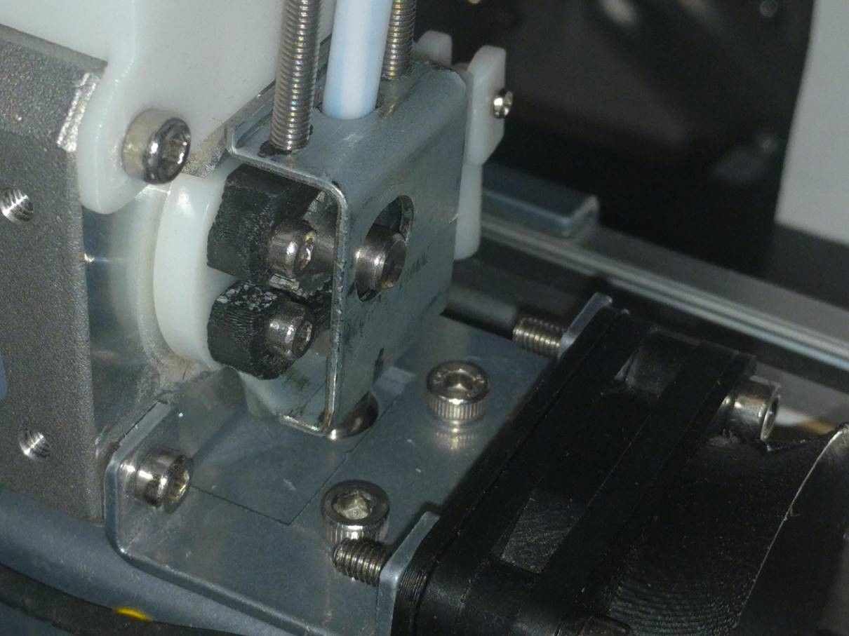
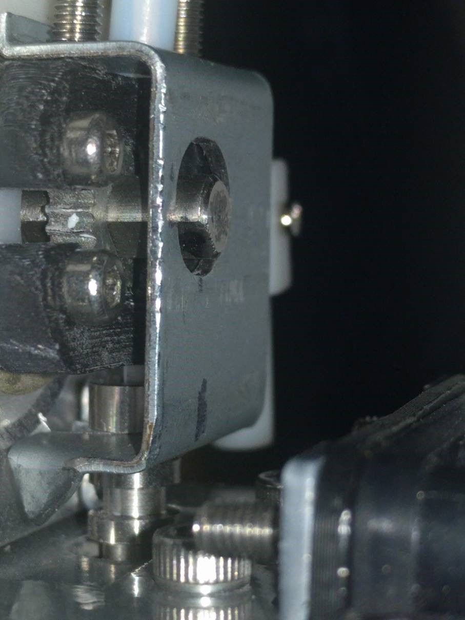
I have designed a smal but effective bracket that supports the Z-axis on the Cetus.
The fit may vary sepending on the version of Cetus and when it was manufactured.But it is pretty easy to draw one, if it does not fit.
-
@fotomas
Thanks good tip.If you have some sheet metal capability, an excellent mod is a bracket to stabilize the nozzle cold end to the extruder. This reduces/eliminates any nozzle height change with extrusion pressure caused by filament temperature, layer thickness, filament retraction etc. Missing in my pic is a spacer washer between the cold end top and the printed part bottom.
-
@Peter120
Many thanks for this. Going to test it out over the weekend.
I notice you are not setting tpwmthrs on M569. Are you motors noisy? -
@skezo
I am no expert just hacked away until I was satisfied.
Switching between stepper driving modes has the potential of a slipped step so I decided to not test changing modes on the fly.The steppers loudness changes depending on the commanded micro step (static) position. It sounds like white noise, my guess is the stepper winding is microphonic and the noise source is the TMC switching driver current. The bed behaves somewhat like a speaker so its stepper is the most noticeable sound. For totally silent printing I would plan on building a heated enclosure.
-
@Peter120
Thanks again for the config file it has helped a lot. I think I am in a place now that I can start tuning and tweaking.Do you have any recommendations on slicers?
-
@skezo
Again no expert but all the slicers that I have tested have quirks.
The Tiertime software environment/slicer is good for beginners and a clever advanced user can work around most limitations. I briefly tested the beta Catfish slicer attempting to get around a bug. Finally reported the bug in detail but it was never fixed. They say Catfish will eventually generate Gcode for other printers but I have moved on.
A good friend who purchased a slicer says don't waste the money.
Tested Cura for two months and was disappointed.
Tested PrusaSlicer for many months. I like it well enough and continue to use it. It is not perfect but believe it currently has the most development momentum.
I design with fusion 360 but have only looked at the fusion 360 slicer. It has the great potential of using finite element analysts to tailor the infill for minimum weight with maximum strength. This is not something that I need but for industrial printed parts this feature would be a winner. -
@Peter120 thanks for the help. I have managed to get a few decent prints.
After running some test I now understand why the bracket to stabilize the nozzle cold end to the extruder mod would be excellent. I can see the nozzle lift considerably during the print.
Do you have any more photos or details you would be willing to share on how to set up this mod?
-
A quick simple build and not fancy, honestly it is a prototype that worked fine.
Made from scrap steel 1mm thick that I had laying around. It was cut to size with a hack saw then clamped in a vice and bent using a hammer. The bolts are long because I had them and the bracket is tapped for them. A cordless drill made all the holes. If the sheet metal were a bit thicker say 1.75mm the extra bends I made to stiffen the bracket would not be needed. I cut a 2mm wide slot to the top and bottom filament feed holes so the bracket can be removed to clean the filament drive gear. I used a bunch small washers stacked to make the spacer between the nozzle top to the extruder bottom and for convince glued them together.
Have fun.