Duet3D Logo Duet3D
    • Tags
    • Documentation
    • Order
    • Register
    • Login

    Duet3 Expansion Board 3HC - No CAN-Connection

    Scheduled Pinned Locked Moved
    Duet Hardware and wiring
    6
    50
    1.9k
    Loading More Posts
    • Oldest to Newest
    • Newest to Oldest
    • Most Votes
    Reply
    • Reply as topic
    Log in to reply
    This topic has been deleted. Only users with topic management privileges can see it.
    • A Former User?
      A Former User
      last edited by A Former User

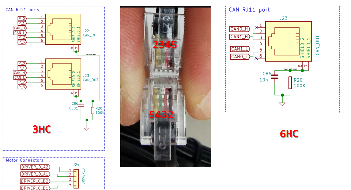
      CAN H and L should not be crossed (twisted pair does not cross the pins). So pin 3 from the 6HC to pin 3 on the 3HC, but @CR3D shows cabling that connet 5 to 1, and 3 to 4 so thats wrong.

      f299f99f-8684-4d6b-84d1-20bd7574e974-image.png

      Chrissundefined CR3Dundefined 2 Replies Last reply Reply Quote 0
      • Chrissundefined
        Chriss @A Former User
        last edited by

        @bearer I can tell only what I did and that works for me. So pin 1 is pin 1, pin 4 is pin4 and the two in the middle is crossed. At least at my working setup. Im on the sofa with my tablet. So im a bit limited.....

        A Former User? 1 Reply Last reply Reply Quote 0
        • A Former User?
          A Former User @Chriss
          last edited by

          @Chriss if your way was right it would work for OP.. the black and yellow are not used by the 3HC, and the green and red are (incorrectly) crossed over.

          1 Reply Last reply Reply Quote 0
          • Chrissundefined
            Chriss
            last edited by Chriss

            Hmmmmm....
            https://duet3d.dozuki.com/Wiki/Getting_Started_With_Duet_3
            Says
            Only a single twisted pair is required, connected to pins 3 and 4 (the middle 2 pins) of the connector.

            But yours seems crossed to me. (Yes I had to correct my former words.)

            1 Reply Last reply Reply Quote 0
            • A Former User?
              A Former User
              last edited by

              So the lower connector in OPs photo is correct if you want to be pedantic about colour coding, but top one is reversed. Easier to check the colours if you flip one end up side down so the pins line up 1:1, 2:2 etc.

              In any case @CR3D needs to swap the red and green wires on one end of his cable.

              CR3Dundefined 1 Reply Last reply Reply Quote 1
              • CR3Dundefined
                CR3D @A Former User
                last edited by

                @bearer

                Ok thank you very much! I will test it 🙂

                Christian from CR-3D
                Homepage:
                www.cr-3d.de

                Facebook:
                https://www.facebook.com/cr3d.official

                Our Discord Server
                https://discord.gg/SxRaPNuRdA

                Thingiverse Profile:
                https://www.thingiverse.com/cr-3d_official/about

                1 Reply Last reply Reply Quote 0
                • CR3Dundefined
                  CR3D @A Former User
                  last edited by

                  @bearer

                  Which cable did you buy? I can not find a right one at the moment...

                  Christian from CR-3D
                  Homepage:
                  www.cr-3d.de

                  Facebook:
                  https://www.facebook.com/cr3d.official

                  Our Discord Server
                  https://discord.gg/SxRaPNuRdA

                  Thingiverse Profile:
                  https://www.thingiverse.com/cr-3d_official/about

                  A Former User? deckingmanundefined 2 Replies Last reply Reply Quote 0
                  • A Former User?
                    A Former User @CR3D
                    last edited by A Former User

                    @CR3D said in Duet3 Expansion Board 3HC - No CAN-Connection:

                    Which cable did you buy? I can not find a right one at the moment...

                    I didn't, don't have an expansion but I would just terminate my own as needed (already have the tools for RJ45 so it will do RJ11, RJ12 and RJ14 as well).

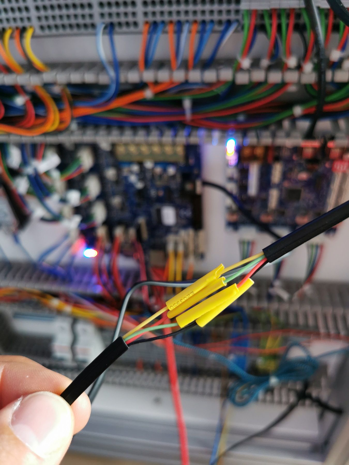
                    But if you purchased the cable made like that, that is a little surprisng, not a standard setup for phones afaik. Aaaanyways, what you can do as a work-around is just cut one end off, strip the insulation back and connect the green to red, and red to green as demonstrated by my brother with an RJ45 jack here:
                    a9971a14-3848-4611-85f8-a7c6943c5a41-image.png
                    (and then as he did, invite a friend with the tools to come fix it later:)

                    CR3Dundefined 1 Reply Last reply Reply Quote 0
                    • deckingmanundefined
                      deckingman @CR3D
                      last edited by

                      @CR3D said in Duet3 Expansion Board 3HC - No CAN-Connection:

                      Which cable did you buy? I can not find a right one at the moment...

                      DC42's commendation is to use high speed ADSL2 cables such as these https://www.kenable.co.uk/en/computer-cables-peripherals/adsl-rj11-cables/7935-adsl-2-high-speed-broadband-modem-cable-rj11-to-rj11-05m-black-007935-5055383479351.html

                      Ian
                      https://somei3deas.wordpress.com/
                      https://www.youtube.com/@deckingman

                      1 Reply Last reply Reply Quote 0
                      • CR3Dundefined
                        CR3D @A Former User
                        last edited by

                        @bearer

                        I made the same today... and it works!!!!

                        Thank you a lot

                        IMG_20200623_134135.jpg

                        Now I have other "Problems"... but I am not sure. Perhabs I should open a new Thread....

                        Christian from CR-3D
                        Homepage:
                        www.cr-3d.de

                        Facebook:
                        https://www.facebook.com/cr3d.official

                        Our Discord Server
                        https://discord.gg/SxRaPNuRdA

                        Thingiverse Profile:
                        https://www.thingiverse.com/cr-3d_official/about

                        1 Reply Last reply Reply Quote 0
                        • A Former User?
                          A Former User
                          last edited by

                          (you didn't need the black and yellow, but it won't hurt either)

                          if its still CAN related you'll probably still attract the right people, if not move to another thread as it makes it easier for the community to help you

                          CR3Dundefined 1 Reply Last reply Reply Quote 0
                          • CR3Dundefined
                            CR3D @A Former User
                            last edited by

                            @bearer

                            To be honest, I don't know what it has to do with it yet.
                            But it still has to do with the 3HC.

                            I connected 9 motors to my printer.
                            It is a Cartesian with triple Z-axis and IDEX system

                            Motherboard:
                            3x Z-axis
                            1x X-axis
                            2x extruders

                            Expansion board
                            1x U-axis
                            2x Y-axis

                            90857944-94df-4668-ab6a-aaa4d849b032-image.png

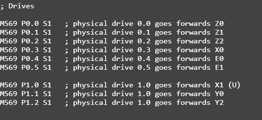
                            The endstops are connected to the mainboard:
                            e3367759-2e48-46e3-b62c-5f411c708d03-image.png

                            The drives which are attached to the mainboard work wonderfully. Even if I check the limit switches, the signals are correct. However, the homing of the U-axis and the Y-axis is not yet working properly.

                            The Homing File of the U-Axis looks like the X-Axis.

                            The motors rotate very slowly and do not react correctly to the limit switch. even if homing is canceled, the motors continue to rotate ...

                            I can't really explain it to myself honestly ...

                            Christian from CR-3D
                            Homepage:
                            www.cr-3d.de

                            Facebook:
                            https://www.facebook.com/cr3d.official

                            Our Discord Server
                            https://discord.gg/SxRaPNuRdA

                            Thingiverse Profile:
                            https://www.thingiverse.com/cr-3d_official/about

                            JoergS5undefined 1 Reply Last reply Reply Quote 0
                            • A Former User?
                              A Former User
                              last edited by

                              if i'm reading that right you have the endstops on the main board?

                              ref https://duet3d.dozuki.com/Wiki/Duet_3_firmware_configuration_limitations

                              CR3Dundefined 1 Reply Last reply Reply Quote 0
                              • CR3Dundefined
                                CR3D @A Former User
                                last edited by

                                @bearer

                                Yes, I had that in mind!

                                I had already tested putting these endstops on the expansion board. So far the same problem .. but I can test it again ...

                                Christian from CR-3D
                                Homepage:
                                www.cr-3d.de

                                Facebook:
                                https://www.facebook.com/cr3d.official

                                Our Discord Server
                                https://discord.gg/SxRaPNuRdA

                                Thingiverse Profile:
                                https://www.thingiverse.com/cr-3d_official/about

                                A Former User? 1 Reply Last reply Reply Quote 0
                                • JoergS5undefined
                                  JoergS5 @CR3D
                                  last edited by JoergS5

                                  @CR3D if you use RRF3, M574 S0 is no longer supported: "Endstop type S0 (active low switch) is no longer supported in M574 commands." please check https://duet3d.dozuki.com/Wiki/Gcode#Section_M574_Set_endstop_configuration and use S1 with ! instead.

                                  CR3Dundefined 1 Reply Last reply Reply Quote 0
                                  • A Former User?
                                    A Former User @CR3D
                                    last edited by

                                    @CR3D said in Duet3 Expansion Board 3HC - No CAN-Connection:

                                    So far the same problem

                                    post the config for that when you do, copy past the text and use the formatting function here makes it much easier to read. (on the toolbar with bold, italics, its the fifth from the left to format as code which makes it nice and readable)

                                    1 Reply Last reply Reply Quote 0
                                    • CR3Dundefined
                                      CR3D @JoergS5
                                      last edited by

                                      @JoergS5

                                      Okay, thanks for the hint.

                                      but it worked fine on the X-axis ...

                                      Christian from CR-3D
                                      Homepage:
                                      www.cr-3d.de

                                      Facebook:
                                      https://www.facebook.com/cr3d.official

                                      Our Discord Server
                                      https://discord.gg/SxRaPNuRdA

                                      Thingiverse Profile:
                                      https://www.thingiverse.com/cr-3d_official/about

                                      1 Reply Last reply Reply Quote 0
                                      • CR3Dundefined
                                        CR3D
                                        last edited by

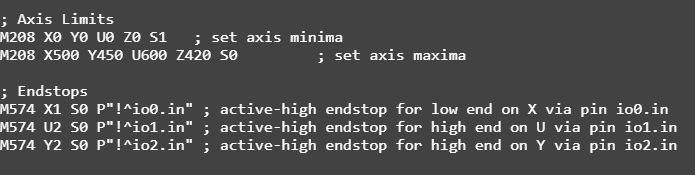
                                        I have now connected the endstops of the Y-Axis and those of the U-Axis on the 3HC ... unfortunately without success ...

                                        Here is the config...

                                        Main:

                                        ; Configuration file for Duet 3 (firmware version 3)
                                        
                                        
                                        ; General preferences
                                        G90            ; send absolute coordinates...
                                        M82            ; and absolute extruder moves
                                        M550 P"I444-S" ; set printer name
                                        
                                        ; Network
                                        M552 S1        ; enable network 
                                        M586 P0 S1     ; enable HTTP
                                        M586 P1 S0     ; disable FTP
                                        M586 P2 S0     ; disable Telnet
                                        
                                        ; Drives
                                        
                                        M569 P0.0 S1   ; physical drive 0.0 goes forwards Z0
                                        M569 P0.1 S1   ; physical drive 0.1 goes forwards Z1
                                        M569 P0.2 S1   ; physical drive 0.2 goes forwards Z2
                                        M569 P0.3 S1   ; physical drive 0.3 goes forwards X0
                                        M569 P0.4 S1   ; physical drive 0.4 goes forwards E0
                                        M569 P0.5 S1   ; physical drive 0.5 goes forwards E1
                                        
                                        M569 P1.0 S1   ; physical drive 1.0 goes forwards X1 (U)
                                        M569 P1.1 S1   ; physical drive 1.0 goes forwards Y0
                                        M569 P1.2 S1   ; physical drive 1.0 goes forwards Y2
                                        
                                        
                                        M584 X0.3 Y1.1:1.2 U1.0 Z0.0:0.1:0.2 E0.4:0.5  ; set drive mapping
                                        M350 X16 Y16:16 Z16:16:16 E16:16 I1  ; configure microstepping 
                                        M92 X80.00 Y35.56:35.56 Z4000:4000:4000 E415:415 ;set steps per mm
                                        M566 X900 Y900:900 Z12:12:12 E120:120   ;set maximum instantaneous speed changes (mm/min)
                                        M203 X30000 Y30000:30000 Z300:300:300 E9000:9000      ;set maximum speeds (mm/min)
                                        M201 X1000 Y1000:1000 Z20:20:20 E1000:1000            ;set accelerations (mm/s^2)
                                        M906 X1400 Y4200:4200 Z1200:1200:1200 E1000:1000 I30  ;set motor currents (mA)
                                        M84 S30               ; Set idle timeout
                                        
                                        ; Axis Limits
                                        M208 X0 Y0 U0 Z0 S1   ; set axis minima
                                        M208 X500 Y450 U600 Z420 S0         ; set axis maxima
                                        
                                        ; Endstops
                                        M574 X1 S1 P"!io0.in" ; active-high endstop for low end on X via pin io0.in
                                        M574 U2 S1 P"!1.io1.in" ; active-high endstop for high end on U via pin io1.in
                                        M574 Y2 S1 P"!1.io2.in" ; active-high endstop for high end on Y via pin io2.in


                                        ; Z-Probe (Piezo)
                                        M558 P5 I1 C"io3.in" R0.5 H5 F400 6000 ; Z probe type -> Piezo
                                        
                                        M557 X120:400 Y20:400 P04:04      ; define mesh grid
                                        
                                        ; Heaters
                                        M308 S0 P"temp0" Y"thermistor" T100000 B4092          ; configure sensor 0 as thermistor on pin temp0
                                        M950 H0 C"out0" T0                                    ; create bed heater output on out0 and map it to sensor 0
                                        M307 H0 B0 S1.00                                      ; disable bang-bang mode for the bed heater and set PWM limit
                                        M140 H0                                               ; map heated bed to heater 0
                                        M143 H0 S120                                          ; set temperature limit for heater 0 to 120C
                                        
                                        M308 S1 P"temp1" Y"thermistor" T100000 B4725 C7.06e-8 ; configure sensor 1 as thermistor on pin temp1
                                        M950 H1 C"out1" T1                                    ; create nozzle heater output on out1 and map it to sensor 1
                                        M307 H1 B0 S1.00                                      ; disable bang-bang mode for heater  and set PWM limit
                                        
                                        M308 S2 P"temp2" Y"thermistor" T100000 B4725 C7.06e-8 ; configure sensor 2 as thermistor on pin temp2
                                        M950 H2 C"out2" T2                                    ; create nozzle heater output on out2 and map it to sensor 2
                                        M307 H2 B0 S1.00                                      ; disable bang-bang mode for heater  and set PWM limit
                                        
                                        ; Fans
                                        M950 F0 C"out7" Q500                                  ; create fan 0 on pin out7 and set its frequency
                                        M106 P0 S0 H1 T50                                     ; set fan 0 value. Thermostatic control is turned on
                                        M950 F1 C"out8" Q500                                  ; create fan 1 on pin out8 and set its frequency
                                        M106 P1 S1 H2 T50                                     ; set fan 1 value. Thermostatic control is turned on
                                        M950 F2 C"out4" Q500                                  ; create fan 2 on pin out4 and set its frequency
                                        M106 P2 S1 H-1                                        ; set fan 2 value. Thermostatic control is turned off
                                        M950 F3 C"out5" Q500                                  ; create fan 3 on pin out5 and set its frequency
                                        M106 P3 S1 H-1                                        ; set fan 3 value. Thermostatic control is turned off
                                        
                                        ; Tools
                                        M563 P0 S"Links" D0 H1 F0:2  ; define tool 0
                                        G10 P0 X0 Y0 Z0 S0 R0        ; set tool 0 axis offsets
                                        G10 P0 R0 S0                 ; active and standby temperatures 
                                        M563 P1 S"Rechts" D1 H2 X3 F0:3   ; define tool 1
                                        G10 P1 Y0 U0 Z0 S0 R0        ; set tool 1 axis offsets
                                        G10 P1 R0 S0                 ; active and standby temperatures 


                                        ; Custom settings are not defined
                                        
                                        ; Open Door Switch
                                        M581 T0 C"1.io3.in"  S0 C0		;trigger #2 (calls trigger2.g)
                                        
                                        
                                        ; LED
                                        M950 F3 C"out3" Q500  ; create fan 3 on pin out5 and set its frequency
                                        M106 P3 S1     ;set fan 3 value. Thermostatic control is turned off


                                        ; Miscellaneous


                                        M501          ; load saved parameters from non-volatile memory
                                        
                                        T0            ; select first tool
                                        
                                        M572 D0 S0.03
                                        

                                        The X-Homing is working:

                                        ; homex.g
                                        ; called to home the X axis
                                        ;
                                        ; generated by RepRapFirmware Configuration Tool v3.1.3 on Fri Jun 19 2020 21:08:48 GMT+0200 (Mitteleuropäische Sommerzeit)
                                        G91               ; relative positioning
                                        G1 H2 Z5 F6000    ; lift Z relative to current position
                                        G1 H1 X-505 F1800 ; move quickly to X axis endstop and stop there (first pass)
                                        G1 H2 X5 F6000    ; go back a few mm
                                        G1 H1 X-505 F360  ; move slowly to X axis endstop once more (second pass)
                                        G1 H2 Z-5 F6000   ; lower Z again
                                        G90               ; absolute positioning
                                        

                                        The Y Homing is not working for example:

                                        ; homey.g
                                        ; called to home the Y axis
                                        ;
                                        ; generated by RepRapFirmware Configuration Tool v3.1.3 on Fri Jun 19 2020 21:08:48 GMT+0200 (Mitteleuropäische Sommerzeit)
                                        G91              ; relative positioning
                                        G1 H2 Z5 F6000   ; lift Z relative to current position
                                        G1 H1 Y455 F1800 ; move quickly to Y axis endstop and stop there (first pass)
                                        G1 H2 Y-5 F6000  ; go back a few mm
                                        G1 H1 Y455 F360  ; move slowly to Y axis endstop once more (second pass)
                                        G1 H2 Z-5 F6000  ; lower Z again
                                        G90              ; absolute positioning
                                        

                                        The U-Axis also...

                                        and I think the motors have hardly any power ... so those that are connected to the 3HC ..

                                        Christian from CR-3D
                                        Homepage:
                                        www.cr-3d.de

                                        Facebook:
                                        https://www.facebook.com/cr3d.official

                                        Our Discord Server
                                        https://discord.gg/SxRaPNuRdA

                                        Thingiverse Profile:
                                        https://www.thingiverse.com/cr-3d_official/about

                                        1 Reply Last reply Reply Quote 0
                                        • CR3Dundefined
                                          CR3D
                                          last edited by

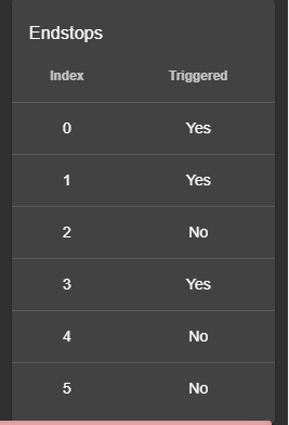
                                          the limit switches are displayed correctly ...

                                          78a55f90-7f37-4435-b0bb-7d0ebbeca2c9-image.png

                                          Christian from CR-3D
                                          Homepage:
                                          www.cr-3d.de

                                          Facebook:
                                          https://www.facebook.com/cr3d.official

                                          Our Discord Server
                                          https://discord.gg/SxRaPNuRdA

                                          Thingiverse Profile:
                                          https://www.thingiverse.com/cr-3d_official/about

                                          JoergS5undefined 1 Reply Last reply Reply Quote 0
                                          • JoergS5undefined
                                            JoergS5 @CR3D
                                            last edited by JoergS5

                                            @CR3D but now this could be valid? "Endstop switches connected to the main board cannot control motors on an expansion board. This is planned to be fixed in release 3.2.0." from https://duet3d.dozuki.com/Wiki/Duet_3_firmware_configuration_limitations

                                            Endstops are on the main board, the steppers for U and Y on the expansion board. X is both on main board. Would explain X working, U and Y not.

                                            1 Reply Last reply Reply Quote 0
                                            • First post
                                              Last post
                                            Unless otherwise noted, all forum content is licensed under CC-BY-SA