PINDA V2 thermistor configuration
-
Hello forum (hopefully the right sub forum)
I‘m trying to configure my Duet 2 WiFi to use the built in thermistor of my PINDA probe as this is supported with RRF 3.
Then I want to use it for Z offset temperature compensation for G31 as the probe reads different Z values depending on it’s temperature.The gcode I use for the thermistor which is connected to thermistor 7 on the expansion port:
M308 S2 P"exp.thermistor_7" A"PINDA" Y"thermistor" T120000 B4725
The temperature reads 2000°C and jumps to 354.8°C and also 1160°C.
Adding or removing zeros to the T value does not help.
My whole config:
; General preferences G90 ; Send absolute coordinates... M83 ; ...but relative extruder moves ; Network M550 P"Pruset II MK3s" ; Set machine name M552 S1 ; Enable network ;M552 S2 ; Enable AP ;*** Access point is configured manually via M587 M586 P0 S1 ; Enable HTTP M586 P1 S0 ; Disable FTP M586 P2 S0 ; Disable Telnet M575 P1 S1 B57600 ; Panel Due ; Drive Mappings M569 P0 S1 ; Drive 0 goes forwards: X Axis M569 P1 S0 ; Drive 1 goes backwards: Y Axis M569 P2 S1 ; Drive 2 goes backwards: Z Axis M569 P3 S1 ; Drive 3 goes forwards: E Axis M569 P4 S1 ; Drive 4 goes backwards: Z Axis (at E1) ; Micrpstepping and Speed M350 X16 Y16 E16 Z16 I1 ; Configure microstepping with interpolation M92 X200.00 Y200.00 Z400.00 E415.00 ; Set steps per mm M566 X480.00 Y480.00 Z24.00 E300.00 P1 ; Set maximum instantaneous speed changes (mm/min) M203 X12000.00 Y12000.00 Z720.00 E1500.00 ; Set maximum speeds (mm/min) M201 X2500.00 Y2500.00 Z1000.00 E2000.00 ; Set accelerations (mm/s^2) M906 X620.00 Y620.00 Z550.00 E500.00 I10 ; Set motor currents (mA) and motor idle factor in percent M84 S30 ; Set idle timeout ; Motor remapping for dual Z and axis Limits M584 X0 Y1 Z2:4 E3 ; two Z motors connected to driver outputs Z and E1 M671 X-37:287 Y0:0 S10 ; leadscrews at left (connected to Z) and right (connected to E1) of X axis M208 X0:250 Y-4:212.5 Z-0.1:205 ; X carriage moves from 0 to 250, Y bed goes from 0 to 210 M564 H0 ; allow unhomed movement ; Endstops for each Axis M574 X1 S3 ; Set endstops controlled by motor load detection M574 Y1 S3 ; Set endstops controlled by motor load detection ; Stallgaurd Sensitivy M915 X S3 F0 H400 R1 ; Set X axis Sensitivity M915 Y S3 F0 H400 R1 ; Set y axis Sensitivity ; Z-Probe PINDA M574 Z1 S2 ; Set endstops controlled by probe M558 P5 C"^zprobe.in" I1 H0.9 F1000 T6000 A20 S0.005 ; PINDA M308 S2 P"exp.thermistor_7" A"PINDA" Y"thermistor" T120000 B4725 G31 P1000 X23 Y5 Z1.025 ; PEI Sheet Offset ;G31 P1000 X23 Y5 Z1.355 ; Textured Sheet Offset M557 X24:221 Y10:195 P12 ; Define mesh grid ; Heatbed Heaters and Thermistor Bed M308 S0 P"bed_temp" Y"thermistor" T100000 B4138 R4700 ; Set thermistor + ADC parameters for heater 0 Bed M950 H0 C"bedheat" T0 ; Creates Bed Heater M307 H0 A128.0 C498.9 D4.5 V24.0 B0 ; Bed PID Calibration and PWM M140 H0 M143 H0 S120 ; Set temperature limit for heater 0 to 120C Bed ; Filament Sensor Port and Loading Feature ON M950 J1 C"e0stop" ; Input 1 e0 Filament Sensor M581 P1 T2 S0 R0 ; Filament Sensor P1 triggers Trigger2.g always (R0) ; HotEnd Heaters and Thermistor HotEnd M308 S1 P"e0_temp" Y"thermistor" T100000 B4725 R4700 ; Set thermistor + ADC parameters for heater 1 HotEnd M950 H1 C"e0heat" T1 ; Create HotEnd Heater M307 H1 A566.8 C170.6 D5.7 V23.9 B0 ; HotEnd PID Calibration and PWM M143 H1 S300 ; Set temperature limit for heater 1 to 280C HotEnd M302 S195 R195 ; Fans M950 F1 C"Fan1" Q250 ; Creates HOTEND Fan M106 P1 T45 S255 H1 ; HOTEND Fan Settings M950 F0 C"Fan0" Q250 ; Creates PARTS COOLING FAN M106 P0 H-1 ; Set fan 1 value, PWM signal inversion and frequency. Thermostatic control is turned off PARTS COOLING FAN ; Tools M563 P0 D0 H1 F0 ; Define tool 0 G10 P0 X0 Y0 Z0 ; Set tool 0 axis offsets G10 P0 R0 S0 ; Set initial tool 0 active and standby temperatures to 0C -
If figured it out by trial and error.
Now I'm using the E1 thermistor port. I don't know why I couldn't use the exp.thermistor 7 port.New setup:
M308 S2 P"e1_temp" A"PINDA" Y"thermistor" T100000 B3950
G31 P1000 X23 Y5 Z1.025 C0.0010 S20 H2		; PEI Sheet Offset
The same issue I had with the Z probe. I wanted to use another port (not Z probe in) but the FW just responded "no probe".
Maybe I did get the documentation wrong and things aren't freely mappable as I think they are. -
@Argo I don't think you can just plug a thermistor into the expansion header; it doesn't have the required circuitry. That's on the Duex board. Thermistors work by having a 'voltage divider' circuit, with a reference voltage (ADVREF on Duet). This is the circuit diagram for the Duet 2 Wifi for the thermistors; you can see Thermistors 0, 1 and 2 have a resistor and connection to ADREF, which Thermistors 3 to 7 don't have this:
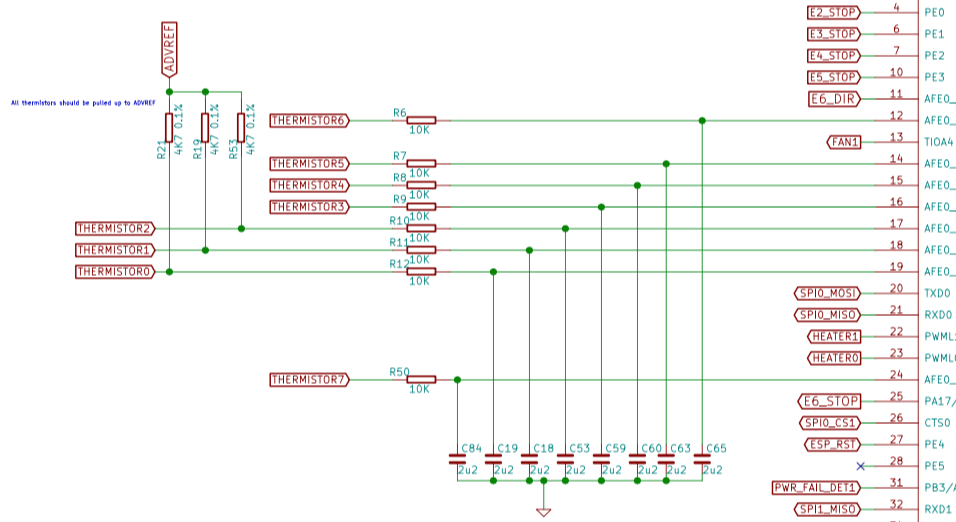
The circuit is quite easy to build, with a 4K7 resistor and a connection to ADVREF (pin 41 on the expansion header).
Not sure why you couldn't connect the Z probe to a different pin, though it may depend which pin you were trying to connect it to. Otherwise, configuration issue?
Ian
-
Thank your for the explanation!
That makes a lost sense then. I must have missed that in the documentation.I think I read somewhere that you can only chose between specific ports on Duet 3 for the Z probe but only the Z probe input for the probe on the Duet 2, but I might be wrong with that.
-
Were you using the Prusa Pinda V2 probe? Did it work with the temperature compensation? Can you share the wiring and the GCode used to set it up? Thanks
-
I've upped my Config. You can copy the things you need.
https://www.file-upload.net/download-14164086/Config.zip.htmlIf you intent to use the whole config: You will need to add this in your start gcode in your slicer software for the filament runout sensor:
; Prime Filament Sensor for Runout
M581 P1 T2 S-1 R0 ; Filament Sensor P1 triggers Trigger2.g always (R0)  TRIGGER OFF
M950 J1 C"nil" ; Input 1 e0 Filament Sensor
M591 D0 P2 C"e0stop" S1 ; Filament Runout Sensor
The reason for this is that I wrote a filament autoload script and you can't have runout detection and autoload enabled at the same time without conditional code.
For the PINDA:
Black is the signal for the probe and goes into Z Probe in.
I connected 5V and GRND to the expansion port pins.
Thermistor is connected to E1You can read out the PINDA thermistor temperature but we'll have to wait for conditional code being implemented as the temperature compensation feature as it is right now assumes that the inaccuracy is linear.
-
Argo,
Thanks much for that! Which board are you using with this config?
All the best!
-
@Kolbi said in PINDA V2 thermistor configuration:
Argo,
Thanks much for that! Which board are you using with this config?
Configuration file for Duet WiFi (firmware version 1.21)
I saw different bin files for Duet3 and Maestro in the archive and it threw me off
")
-
Sorry the comment section is a bit old in my config ^^
RRF 3.11 and Duet WiFi
-
@Argo No sorrys needed - you definitely got me way further along with my setup!
-
@Argo Thanks for the info. I have PINDA v2 on order so this will help me once I get it installed.
-
Argo,
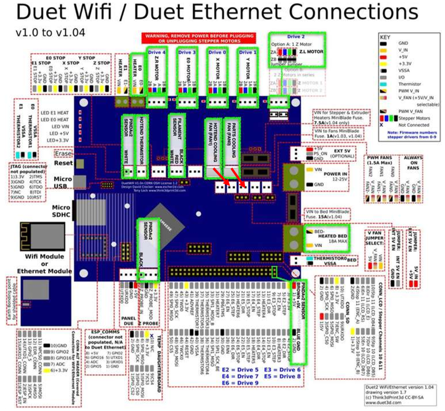
Looking at your config and postings I believe the attached graphic, WITH EXCEPTION OF FANS, depicts your wiring configuration - can you confirm please?
I Drew this up before work, flubbed the fan locations - they have to go one row down and move to the 2nd and 3rd connector on the board, corresponding to FAN1(2nd) and FAN0(3rd). I'll correct this after work.Thanks much
-
E0 endstop (filament sensor) is the 1st in the row not the second.
-
@Argo Ah... When looking at the top-left endstop block, I read it as E1-E0-EX-EY-EZ?
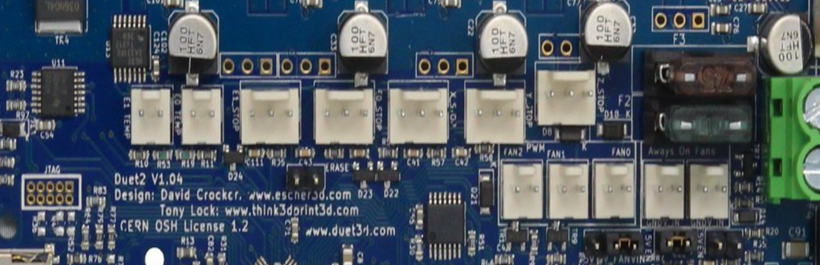
So do you have the filament sensor plugged into the first endstop?
-
Good you have a photo of it unplugged. Seeing through all the cables of my board I thought it’s the first one I connected.
So yes you are right it’s the second for E0. -
The corrected wiring overview.

I'm working on a step-by-step guide, once done I'll post it.
V/R,
Kolbi -
I installed the Duet wifi on my Prusa MK3s this past weekend, no issues at. She got the Zaribo 10mm full upgrade as well as Duet wifi so it's really a completely different machine.
For firmware settings, I used @Argo configurations - here
For wiring, I used a guide I created, and now verified - here
Cheers,
Kolbi -
I did just switch the case fan from constant power to fan2 and followed the guide here: https://duet3d.dozuki.com/Wiki/Mounting_and_cooling_the_board#Section_Cooling
M308 S2 Y"drivers" A"DRIVERS"  ; configure sensor 2 as temperature warning and overheat flags on the TMC2660 on Duet
M308 S3 Y"mcu-temp" A"MCU" ; configure sensor 3 as thermistor on pin e1temp for left stepper
M950 F2 C"fan2" Q100 ; create fan 2 on pin fan2 and set its frequency
M106 P2 H2:3 L0.15 X1 B0.3 T40:70 ; set fan 2 value
""""Creates sensors for the driver overtemp flag and the MCU temp reading using M308 as S2 and S3. Creates a fan port for Fan2 with M950. Then creates a fan command to link those sensors to fan2 with a temp range of 4code_text0-70 using M106.""""
*This made the case fan MUCH quieter and with that it only runs when its needed.
