Guide: Pressure Advance Calibration (Bowden tube only!)
-
Pressure Advance Calibration
This is a beginner's guide for calibrating the pressure advance. I'm gonna guide you step by step through the process and I'm gonna show you some tricks that will help you find more easily the right settings.
I suggest reading the complete guide before you start. Why...? There is a lot of information, the information is not always in order to keep the guide clear.
For you to complete this guide in success I assume that your 3D printer is already printing a good product and you want to fine tune the printer for a better printing result.
The next conditions should be considered before following the guide:
I suggest to use Simplify3D with this guide because I can’t promise that any other slicer would slice the object the right way that is needed for this guide. The following settings must be used during this guide, using any other values for this test would undermine the conclusion that follows out of the test.Slicer Settings Nozzle diameter: 0.40mm Extrusion Multiplier: use your own value Extrusion width: 0.48 mm Primary Layer Height: 0.2mm First Layer Height: 100% Internal Fill Pattern: Rectilinear Infill Percentage: 100% Infill Extrusion Width: 100% Outline Overlap: from 10% to 30% should be fineFirst step:
I recommend you start with the PA Cube, it is a square cube by 20x20x20 what you can easily make bigger in Simplify3D with the setting ''Change Scaling''. You need to make the test cube 50x50x50 for this test.In Simplify3D you need a zero top and bottom layer, you need 2 Outline/perimeter shells with zero infill and I suggest a printing height of 20mm. With Skirt/Brim you need an offset of zero and 10 brims for the first layer. You can still make some small adjustments for the first layer height and the brim is wide enough for this test to have absolutely no issues with warping. The beginning and the end of the retracting needs to be aligned to a single point, in Simplify3D this is called the start points. And Ooze Control Behavior needs no check mark. Now you can slice the test cube to a g-code and it's ready for printing.
Second step:
Go to your DWC (duet web controler) and load the program. Wait till the printer start printing and make sure everything goes fine. You have enought time to watch the complete first layer to finish before you have to do the next step.So now use the G-code console and type the following code:
M572 D0 S0.2To make sure that the Pressure Advance is activated you can check the PA by typing the code M572 and you should get a replay stating the amount of pressure advance.
This will only work when you have a Bondtech Extruder mounted!
The next part is maybe confusing but you will get it threw the process, you gonna rise the Pressure Advance with 0.1 (so from S0.2, you take the next step to S0.3, then S0.4.... S0.5 and so forth). There is going to be a change in sound from the bondtech extruder, this sound is going to be an recognizable raw extruder sound and you would think there is something wrong. You stop rising the pressure advance when you recognize the sound and you can let the 3D printer finish it's print.
See video
Second videoWe have now determined the maximum Pressure Advance value. And we can continue to step 3.
Step 3:
Load the PA Infill Test.3MF in Simplify3D.Now change the following in Simplify3D. You need 1 top and 1 bottomlayer, you need 2 Outline/perimeter shells with 100% infill (reticular) and I suggest turning off the printing height of 20mm. With Skirt/Brim you need an offset off 1mm and 6 brims for the first layer.
Turn off the pressure advance with ''M572 D0 S0''. Then you can start the program you just sliced (PA infill test.3FM). Make sure the first layer is good, there is enough time for that. If the first layer is printed and there is a resume off the following layers you can turn on the PA with ‘’M572 D0 S0.2’’. Now you go back to the 3D object being printed and you look at the infill, with the wrong Pressure Advance the infill is going to look bad.
If pressure advance is to low?
The infill would be over extruding. The perimeters would be thin, but keep in mind that the nozzle pressure is too high and it needs time to stabilizeIf pressure advance is too high?
The infill would be under extruding, the perimeters will be too thick but at the start of the print there could be a under extrusion because the filament is pulled back to much with the bad Pressure Advance value.Extra info: With a low- or high-Pressure Advance the nozzle pressure will recover if the Pressure Advance is not being enabled for a certain kind of period while printing. Think about the outside perimeter where you would go around the object without any interruption. In this situation the extrusion could be bad at the beginning but it would recover around halfway the perimeter. But this also depends on how far away you are with finding the right pressure advance.
So, from this point it’s for you to find the right Pressure Advance and if you manage to find the right value then you completed the first few steps.
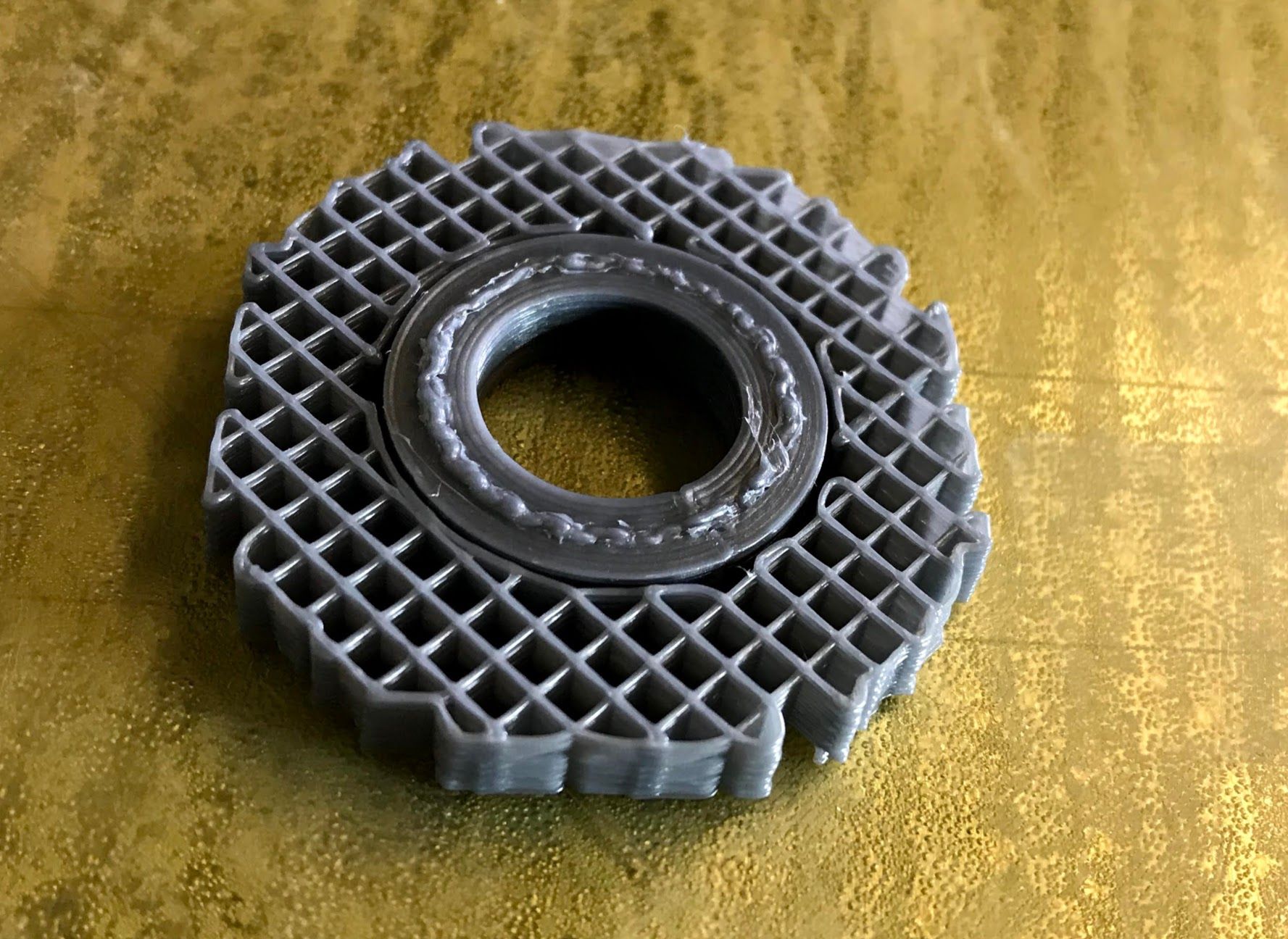
The result should look likes this.
Step 4 (Final calibration):
With the last settings you used in Simplify3D for the PA infill test.3FM you can slice the next part.Use the Pressure Advanced you got from step 3 and see the results. If it goes well then there is no need for adjustments of the Pressure Advance value. If you are not satisfied with the result you can try a different Pressure Advance value.
Step 5:
So, if everything is done correctly we have a the right Pressure Advance value what we can use for printing a product. For this test I suggest printing the PA Box.3MF.After layer 8, (@printing height 1.5mm) the infill will be separated into 2 infills. From this point we have to keep looking at the part being printed and see how the gap infill goes with the Pressure Advance.
Extra Info: Because of the radius inside the box there are going to be a few weird gap infills. Let call these gap infills ‘’exotic gaps’', and with the right Pressure Advance value the printer would fill all these gaps without any problems.
After layer 20 (@Z height of 3.90mm) you can leave the part to finish printing. We have to wait till the print is finished and then we can continue the last process in step 5 were we start measuring the object.
-
The Result
While I was writing this guide, I run the calibration myself. So, in the last part of the Guide ‘'Pressure Advance Calibration’', I would like to show a few things and explain a bit more for a better interpretation.
My printer
This test is done on a Delta printer with a Ø180mm print bed.
A short story: It is a rebuild Tractus T650P. Why rebuild? This printer was running on a fake arduine mega 2560, after a short circuit the Mega2560 burned down. So, I mounted a Duet3D Duet 2 Ethernet and replaced the complete effector. There are still some mechanical issues where Tractus3D falls me short but despite the small problems I fortunately can still print with it.
I have a second 3D printer, a rebuild Prusa MK2.5. In this part of the guide you are going to be hearing a few times for comparison.
Configuration:
; General preferences of the rebuild Tractus T650P

G90						; send absolute coordinates...

M83						; ...but relative extruder moves

M550 P"Godzilla"				; set printer name

M665 R129.16 L229.55 B100 H210			; Set delta radius, diagonal rod length, printable radius and homed height

M666 X0 Y0 Z0					; put your endstop adjustments here, or let auto calibration find them


; Network

M552 P192.168.0.30 S1				; enable network and set IP address

M553 P255.255.255.0				; set netmask

M554 P192.168.0.1				; set gateway

M586 P0 S1					; enable HTTP

M586 P1 S0					; disable FTP

M586 P2 S0					; disable Telnet


; Drives

M569 P0 D2 F2 B2 Y01:09:02 S1			; physical drive 0 (X) goes forwards

M569 P1 D2 F2 B2 Y01:09:02 S0			; physical drive 1 (Y) goes forwards

M569 P2 D2 F2 B2 Y01:09:02 S0			; physical drive 2 (Z) goes forwards

M569 P3 D2 F2 B2 Y01:09:02 S0			; physical drive 3 (E0) goes forwards

M584 X0 Y1 Z2 E3				; set drive mapping

M350 X16 Y16 Z16 E16 I1				; configure microstepping with interpolation

M92 X160.00 Y160.00 Z160.00 E830.00		; set steps per mm

M566 X600.00 Y600.00 Z500.00 E3600.00		; set maximum instantaneous speed changes (mm/min) / also called maximum jerk speed

; M566 X1000.00 Y1000.00 Z1000.00 E3600.00	; set maximum instantaneous speed changes (mm/min) / also called maximum jerk speed

M203 X15000.00 Y15000.00 Z15000.00 E3600.00	; set maximum speeds (mm/min)

M201 X1000.00 Y1000.00 Z1000.00 E3000.00	; set accelerations (mm/s^2)

M906 X1500 Y1500 Z1500 E1500 I50		; set motor currents (mA) and motor idle factor in per cent

M84 S60						; Set idle timeout
; General preferences of the rebuild Prusa MK2.5 G90 ; send absolute coordinates... M83 ; ...but relative extruder moves M550 P"Maestro2Prusa" ; set printer name ; Network M552 P192.168.0.20 S1 ; enable network and set IP address M553 P255.255.255.0 ; set netmask M554 P192.168.0.1 ; set gateway M586 P0 S1 ; enable HTTP M586 P1 S0 ; disable FTP M586 P2 S0 ; disable Telnet ; Drives M569 P0 S1 ; physical drive 0 goes backwards, this is the X-axle M569 P1 S0 ; physical drive 1 goes backwards, this is the Y-axle M569 P2 S0 ; physical drive 2 goes backwards, this is the Z-axle M569 P3 S0 ; physical drive 3 goes backwards, this is the extruder E0 M569 P4 S1 ; physical drive 4 goes forwards, this is the extruder E1 M569 P5 S0 ; physical drive 5 goes backwards, this is the extruder E3 M569 P6 S1 ; physical drive 6 goes forwards, this is the extruder E4 M584 X0 Y1 Z2 E3:4:5:6 ; set drive mapping M350 X16 Y16 Z16 E16:16:16:16 I1 ; configure microstepping with interpolation M92 X100.00 Y100.00 Z400:400 E415.00:830.00:830.00:830.00 ; set steps per mm ; M566 X900.00 Y900.00 Z12.00:12.00 E3600.00:3600.00:3600.00:3600.00 ; set maximum instantaneous speed changes (mm/min) / also called maximum jerk speed M566 X800.00 Y800.00 Z12.00:12.00 E3600.00:3600.00:3600.00:3600.00 ; set maximum instantaneous speed changes (mm/min) / also called maximum jerk speed M203 X12000.00 Y12000.00 Z720.00:720.00 E3600.00:3600.00:3600.00:3600.00 ; set maximum speeds (mm/min) M201 X1000.00 Y1000.00 Z200.00:200.00 E3000.00:3000.00:3000.00:3000.00 ; set accelerations (mm/s^2) M906 X1430 Y1430 Z600 E1260:1260:1260:1260 I30 ; set motor currents (mA) and motor idle factor in per cent M84 S30 ; Set idle timeout*Above you can see my configuration of the 2 printers. There are 2 M566 lines but one is disable with the semicolon (;). I use the disabled M566 line if I want to go back to the original state after a test.
The first time I started this test I run into a few complications during printing what needed adjustments in my configuration settings. I had to lower the jerk settings (M566) on the X and Y axle to get the results I needed with the Pressure Advance
- recognizable raw extruder sound from the Bondtech.
With finding the right value for the Pressure Advance this sound I hear quit often during the test. I found out the sound will appear when you are to high with the Pressure Advance value. But with small gap infill the sound will appear to, but I find it to have a different hearing to it.
Now it gave me problems during printing with finding the right Pressure Advance value. I couldn’t get the infill correct or I had vibrations and ringing or the raw extruder sound coming from the Bondtech. When I started lowering the ''Jerk Settings'' the result would get better, so I just kept lowering till there was no improvement anymore.
And still with this guide I got vibrations and ringing on the PA Box.3MF. I did the same test (with PLA) on a rebuild Prusa MK2.5 where I would find the same problems but here I got a high quality print. The only minor was a bad gap infill during one layer.
So there is still some tweaking and tuning to be done for me after finishing this guide.If you have problems I suggest you start will lowering your jerk settings.
Filament:
The filament that has being used during this guide is from Formfutura, ApolloX (natural)
I use an Multiplier of 0.91, Nozzle is 250 °C, bed is 90 °C
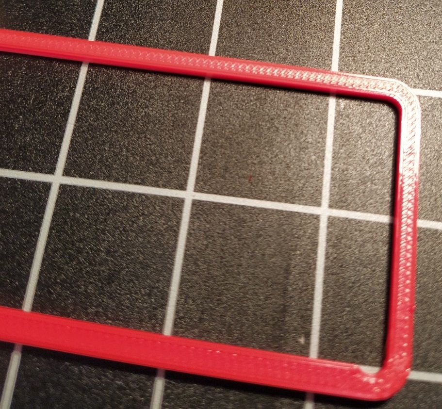
Printed PA Box
My overall impression of the PA Box is good. Good layer adhesion, smooth layers, no artifact. Good dimensions and the looks is pretty.
points of improvement
-
Ringing at the beginning of the extrusion
-
minor under-extrusion with the top infill
-
Last Bit
I found the Pressure Advance Calibration to be a hassle. Where you can find blogs or video’s about calibration your extruder or tuning the heater catridge, there was just a limited information about Pressure Advance calibration.
There is a Duet3D forum Pressure Advance calibration topic. I first started with the script in python, I just did not get a print with a Pressure Advance value that was useful for me. And my experience with that test, I could not get it to work!
Duet3D Wiki Pressure Advance, here I got a Pressure Advance value that could work, but I notice the wide range of value I could use and I would still have a very decent cube.
And actually, because of the Duet3D Wiki I came up with my own test and made this guide. I hope some other godlike fool will use this guide in his new adventure and find this helpful.
A few tips for the guys!
- Get a Bondtech extruder!
Credits:
David Bodanyi, a 3D printing specialist who made this guide possible.
The intern, Thomas Plakké. Did the actual printing in this guide and helped with writing and images.
-
@Scrambler73 Thank you! This guide really helped me a lot in finding the right settings.
Especially the part about reducing xy jerk. That was it!
-
Thanks for this post! I'm at the moment trying to calibrate my Ender 5 Plus with bowden Titan. Not sure how to interpret the results of the python script. Measuring with caliper gives me quite a diffrent result than by looking at the part against the light.
Think I will run through this guide as well. I have rather high jerk at the moment.
-
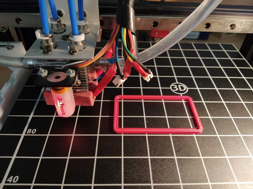
I have run some other tests and 0.76 showed the best seams. Now I'm printing PA_Infill_test scaled 225% because I'm using a 0.8mm nozzle and 0.6mm layer height.
Plastic is PETG printing at 230.
Video link: https://photos.app.goo.gl/6S1EMgKQ9N7D1BVB6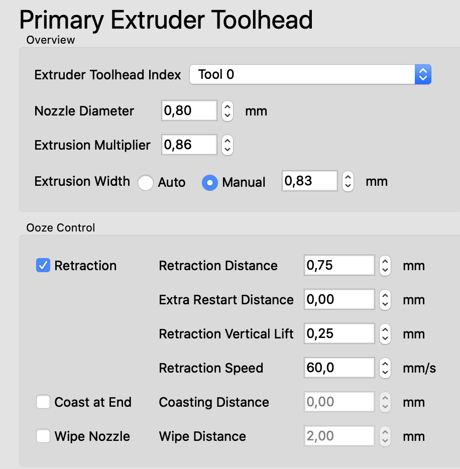


-
I hope you guys don't mind if I hijack this topic, but it fits to my current "dilemma".
I'm having a strange issue with the Pressure Advance feature, and reading most of the topics here on the forum and trying different values, I am still at a lost and don't know exactly how should I proceed.
My setup is as follows:
Duet Wifi 2 controller, Firmware 2.05.1
Bowden around 250mm in lenght, E3D V6, with simple extruder, no gear reduction.
Printing in ABS, 230°CI found my "ideal" pressure advance value to be around 0.35 - 0.4 with sharp corners and start and end lines that are quite consistent in width. In most of my parts, let's say 98% of them, I can find no fault. The rest however, whenever I have a very short travel zig-zag infill, like in the tests presented here in this thread, I get a huge blob of filament, like I would have the extrusion bumped up to 200%. No matter what value I set, everything above 0.05 will give me this effect, even going up to 0.9 or 1.0 . It will stop and print a normal infill if I disable Pressure Advance completely or the value is extremely low, under 0.05 which will effectively disable it for my setup.
What am I doing wrong here ?
Thanks for the help.
-
@unromeo21 I think it would be best to start a new thread with your issue.
-
I'm struggling with pressure advance on my bowden printer as well. Sometimes I see similar behavior to @unromeo21
Even though my bowden is relatively short, and I'm using Bondtech dual drive gears, the S value required to get a straight line segment, with fast and slow sections (20 mm/s - 60mm/s), to print at a consistent width is over S1.2.
For certain print geometry values near or above S1 will work well. But in other areas, the extruder gets hyperactive and extrusion is inconsistent.
I may make a new thread brainstorming ideas that could make the system work better on bowden printers.
-
@CCS86 Pressure advance is by no means perfect. It's an approximation to try and deal with most cases that may not cover the edge cases and extremes very well. Any suggestions for improvement are welcomed.
-
 undefined buzzby referenced this topic
