Dimensions on a printed part
-
I have printed one of the models I mentioned above above and im a little confused by the meassurements.
Here is a picture of the dimensions of the octagon model:
The A and B diagonals are the same length, so that means the belts should be good?
What I don't understand is the diffrence between the X and Y axis. This seems to me like the linear rails are not lined up right? I have checked that several times now and it should be correct

-
Are you using calculated steps per mm or are they derived from measurements?
When you changed to the linear rails did the parallelality (is that even a word?) of the belts change at all?
Can you post a photo of your printer looking down at it from the top to show the belt paths clearly?
-
Im using the default 80 steps/mm. I have made some changes to the extruder steps to tune it in.
I can't say im 100% sure wether the belts changed - they are going in the same form as the old setup, but the angle might be a bit off?
I havent been modelling the parts myself, but if it helps here is a link to what I have been using: https://www.thingiverse.com/thing:2859666
Picture from the top of the printer:


Let me know if I should take pictures from another angle.
Thanks alot for your input!
-
In your first photo the belt paths returning to the carriage don't seem to be parallel with the rail.
-
You're right!
Not really sure where to go from here though.. I need to find out wether its the models that are wrong or if its the printer I printed the parts on that is dialed in wrong. There are no way to adjust the belt angle with the current build
Thanks for spotting the error

-
Correcting the belt path will be the first thing to solve. You'll never get accurate prints with belts like that because the carriage position will vary as it gets closer to the edges as the angle of the belt changes.
What does the carriage look like where the belt attaches? Can you modify it to move it over a bit? You got the parts from thingiverse. Do they also have the source files? What is different in your build from their build?
-
I get that part, and I "know" what to do to fix it, I just lack the experience with modelling parts.
The belts are going through a hole and is clamped down.

By looking through the holes top-down on the X axis rail I can clearly see the belt in the center of the rail where it comes from the Y axis, and is way off center towards X min. I would have to move the hole by 1-2mm.
The reason I thought it could be the parts is just because I have not seen alot of feedback on the remixed parts. I started out with a Hypercube Evolution and moved to HyperCube Fusion, but sinse im using the Zesty Nimble and could not find a mount that would fit it I ended up with a remixed version of the Fusion.
The fusion360 file is uploaded with the project, but I will have to do some learning before beeing able to edit it there. I have only been messing around with simple models in 123D Design.
-
@Jaran said in Dimensions on a printed part:
I would have to move the hole by 1-2mm.
If you can give me an absolute best educated guess on how much it needs to move I can give it a nudge in Fusion 360 for you and upload the STL.
-
That would be fantastic if you have the time!
") However I think there might be an issue with the cad file.
However I think there might be an issue with the cad file.I just tried to open the file myself, and got an error saying "New design cannot be created from a local file containing references". Im guessing this is because its remixed from the "original" Hypercube Fusion design. Is there any way to know whats missing and add it in?
-
Achieving dimensional accuracy isn’t as simple as a single scale measurement. I use S3D for slicing and it has X, Y, Z part scaling plus a horizontal offset. I don’t know IdeaMaker well, but I’m guessing X and Y-axis compensations in the Printer Settings dialog work for XY scale. Part Scaling can also work, although I don’t know why they have chosen Width Depth and Height over X, Y, and Z. Under the OTHER tab, XY size compensation may be the same as S3D’s Horizontal Offset.
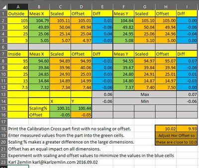
Attached you will find a part I'm calling a Calibration Cross - STL and JPG drawing. It includes internal and external features, both large and small. I have also attached an Excel Spreadsheet (Zipped) which allows you (by trial and error) to see the impact of scaling and horizontal offset values in correcting part dimensions.
Print off a Calibration Cross with no scaling and no horizontal offset. Enter the measured values into the spreadsheet and experiment with different X & Y scale factors as well as the horizontal offset value to minimize the resulting error on all of the measured dimensions. The solver add-in can help narrow in on the best values.
Whenever I’m going to print using a new setup, filament, significantly different print speed, layer height, temperature, etc, I start by running a Calibration Cross and use the spreadsheet to calculate scaling and offset numbers. This technique has proven to be a reliable way to ensure dimensional accuracy on parts. The Z-scale on my N2+ has proven to be quite accurate, so I just use 100% on that.
I can generally achieve part accuracy better than +/- .1mm (.004") on all dimensions.
-
@Jaran said in Dimensions on a printed part:
Is there any way to know whats missing and add it in?
Yes I just ran into the same problem opening it up.
You'd have to have all the referenced files from the hypercube fusion in place alongside it I think. Perhaps you could request the original remixer export a simple step file of the piece in question so it can be more easily modified. Or maybe they can nudge it over the needed 1-2 mm for you.
-
@zemlin Thank you for your input! Im using S3D aswell. This will for sure come in handy, but first I need to get my belts fully aligned. I guess this could fix the issue with the belt if it comes down the the printed part beeing printed wrong, but I don't belive its that much off.
@Phaedrux Tried a bit with the original Hypercube Fusion files but ended up with the same error. I read a few comments on the remix im using from people requesting the cad files aswell, but it seems like the creator has abandoned the design. Im at the point now where I think I might just move over to the original Fusion design and remix the hotend mount plate to suit the holes of the original hotend mount. Should only be 5 holes, I belive that is something I might manage myself
Thanks alot to all of you! I will post back once I have some updates.
-
Great chance to improve your fusion 360 skills.
-
@Phaedrux Sure is! I have been planning to pick it up. The few times I have had the need to model anything I have managed with 123D Design, but with the time I regret opting to that

-
The Lars Christensen videos on youtube are a great way to pick up fusion.
-
@Phaedrux Thank you! I will check his videos out.
-
A little update on this issue:
I have finally swapped out all the parts for the X and Y axis and extended the Z axis to be able to reach the hotend. All in all these new parts feel alot more sturdy and well designed compared to the old parts I had.
I did manage to model up a new mount for the Zesty Nimble im using. As im impatient I gave it a go in 123D Design and it worked out OK. I did not scale the mount holes up enough so it did not fit perfectly. Nothing the dremel couldnt fix...
I had some issues fitting the parts together after snapping the hotend into its place as the part expanded a bit due to the preassure. I ended up breaking off some of the model to actually make it fit. The hotend sits sturdy even without the part I broke off.
The whole setup does not look too nice, but it works. I will try to make it look better with the time.

So, back to the dimensions:
I have only printed a few calibration cubes and will have to do some more tests the following days, but so far it looks promising. The two cubes I have printed came out as 20.05x20.05mm and 20.05x20.05mm, so both came out with identical dimensions. I will print the calibration hexagon tomorrow.
Even though the parts seem better now I still noticed that the belts going for the XY idlers to the hotend itself still seems a bit off like the old setup, though not as much.
-
Back to the drawingboard! Seems like im having the exact same issues with the dimensions when I printed the hexagon. The only change I made was swapping out the filament.
I saw that the belt seem to have the same angle as the old parts. I tried to import the parts into fusion to see how they lined up:
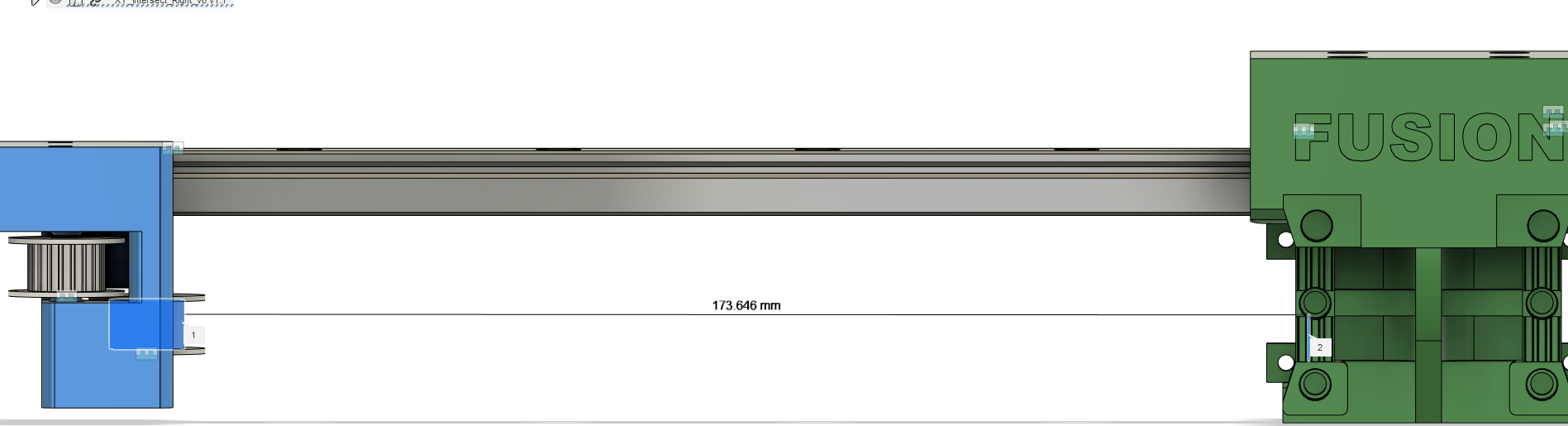
It does not look like the parts are fully lined up. If you look at the right side of the picture you can see the outline of the hole the belt goes into. The line is going from the top of that hole to a bit over center on the idler. Is this enough to make up the problems im having? I just find it weird how nobody else with the design have pointed it out

Is there a way I can verify that it actually is the belt doing it? If I loosen one belt and tighten the other, and vice versa I should see some changes on the dimensions depending on which belt is tight/loose?