Unable to get any stepper motors to work
-
Hi Guys.
I have been unable to get any stepper motors to work. Occasionally they will work as expected (every 20 times I turn them on and off) but most of the time no function whatsoever. I also keep getting the following warning: (
Warning: motor phase A may be disconnected reported by driver(s) 0
Warning: motor phase B may be disconnected reported by driver(s) 0) and also the same for stepper 2.
I have checked the resistance of all my steppers wiring and all looks correct about 2 amps resistance for each phase. Just wondering if it is a config issue. I bought new motors to check if it was perhaps a blown motor but that also didnt work.
new motors = https://www.amazon.co.uk/gp/product/B075JG2MVS/ref=ppx_yo_dt_b_asin_title_o00_s00?ie=UTF8&psc=1CONFIG.G ; Drives M569 P0 S1 ; physical drive 0 goes forwards M569 P1 S1 ; physical drive 1 goes forwards M569 P2 S1 ; physical drive 2 goes forwards M569 P3 S1 ; physical drive 3 goes forwards M584 X0 Y1 Z2 E3 ; set drive mapping M350 X16 Y16 Z16 E16 I1 ; configure microstepping with interpolation M92 X80.00 Y80.00 Z4000.00 E420.00 ; set steps per mm M566 X900.00 Y900.00 Z12.00 E120.00 ; set maximum instantaneous speed changes (mm/min) M203 X6000.00 Y6000.00 Z180.00 E1200.00 ; set maximum speeds (mm/min) M201 X500.00 Y500.00 Z20.00 E250.00 ; set accelerations (mm/s^2) M906 X1000 Y1000 Z1000 E1000 I30 ; set motor currents (mA) and motor idle factor in per cent M84 S30It seems like I'm getting no power delivery to the motors at all (when turned on the motors do not become difficult to turn like they used to).
Here are some more results from a few commandsM584 Driver assignments: X0 Y1 Z2 E3, 3 axes visible M906 Motor current (mA) - X:1000, Y:1000, Z:1000, E:1000, idle factor 30% M913 Motor current % of normal - X:100, Y:100, Z:100, E:100 M122 === Diagnostics === RepRapFirmware for Duet 2 WiFi/Ethernet version 3.1.1 running on Duet WiFi 1.02 or later Board ID: 08DJM-9178L-L2MSD-6JKD2-3S86Q-K9DYN Used output buffers: 3 of 24 (12 max) === RTOS === Static ram: 27980 Dynamic ram: 93572 of which 44 recycled Exception stack ram used: 472 Never used ram: 9004 Tasks: NETWORK(ready,348) HEAT(blocked,1224) MAIN(running,1896) IDLE(ready,80) Owned mutexes: WiFi(NETWORK) === Platform === Last reset 00:05:36 ago, cause: software Last software reset at 2020-08-03 13:00, reason: User, spinning module GCodes, available RAM 9004 bytes (slot 1) Software reset code 0x0003 HFSR 0x00000000 CFSR 0x00000000 ICSR 0x0441f000 BFAR 0xe000ed38 SP 0xffffffff Task MAIN Error status: 0 MCU temperature: min 24.9, current 28.9, max 29.3 Supply voltage: min 12.1, current 12.1, max 12.2, under voltage events: 0, over voltage events: 0, power good: yes Driver 0: standstill, SG min/max not available Driver 1: standstill, SG min/max not available Driver 2: standstill, SG min/max 0/0 Driver 3: standstill, SG min/max not available Driver 4: standstill, SG min/max not available Date/time: 2020-08-03 13:05:51 Cache data hit count 583216538 Slowest loop: 9.06ms; fastest: 0.12ms I2C nak errors 0, send timeouts 0, receive timeouts 0, finishTimeouts 0, resets 0 === Storage === Free file entries: 10 SD card 0 detected, interface speed: 20.0MBytes/sec SD card longest read time 2.1ms, write time 0.0ms, max retries 0 === Move === Hiccups: 0(0), FreeDm: 169, MinFreeDm: 168, MaxWait: 122045ms Bed compensation in use: none, comp offset 0.000 === MainDDARing === Scheduled moves: 15, completed moves: 15, StepErrors: 0, LaErrors: 0, Underruns: 0, 0 CDDA state: -1 === AuxDDARing === Scheduled moves: 0, completed moves: 0, StepErrors: 0, LaErrors: 0, Underruns: 0, 0 CDDA state: -1 === Heat === Bed heaters = -1 -1 -1 -1, chamberHeaters = -1 -1 -1 -1 === GCodes === Segments left: 0 Movement lock held by null HTTP is idle in state(s) 0 Telnet is idle in state(s) 0 File is idle in state(s) 0 USB is idle in state(s) 0 Aux is idle in state(s) 0 Trigger is idle in state(s) 0 Queue is idle in state(s) 0 Daemon is idle in state(s) 0 Autopause is idle in state(s) 0 Code queue is empty. === Network === Slowest loop: 15.63ms; fastest: 0.00ms Responder states: HTTP(2) HTTP(0) HTTP(0) HTTP(0) FTP(0) Telnet(0), 0 sessions HTTP sessions: 1 of 8 - WiFi - Network state is active WiFi module is connected to access point Failed messages: pending 0, notready 0, noresp 0 WiFi firmware version 1.23 WiFi MAC address ec:fa:bc:6f:c6:d6 WiFi Vcc 3.35, reset reason Unknown WiFi flash size 4194304, free heap 25784 WiFi IP address 192.168.1.251 WiFi signal strength -47dBm, reconnections 0, sleep mode modem Socket states: 4 0 0 0 0 0 0 0Thanks in advance
-
@Odin said in Unable to get any stepper motors to work:
Occasionally they will work as expected (every 20 times I turn them on and off)
How are you "turning them on and off"?
I also keep getting the following warning: (
Warning: motor phase A may be disconnected reported by driver(s) 0What are you doing to generate that error?
I have checked the resistance of all my steppers wiring and all looks correct about 2 amps resistance for each phase.
Good that you have checked the phase pairs, but how are they actually wired to the Duet?
Please post your full config.g
For the Z axis, are you sure the steps per mm is 4000?
-
@Phaedrux said in Unable to get any stepper motors to work:
How are you "turning them on and off"?
By them I meant the 3d printer Turning it off and on by the power I have not plugged/unplugged any motor whilst the board is powered. So just as an example I came this morning and turned the printer on and everything worked as expected. Turned it of and back on, still working. I thought oh its fixed itself off and on again... no longer working.
What are you doing to generate that error?
Homing X / Y or moving the motors individually
Good that you have checked the phase pairs, but how are they actually wired to the Duet?
They are wired using the normal X/Y/Z header on the board I have checked the continuity of the wires (crimps) and all looks as expected.
Please post your full config.g
; General preferences
G90                                     ; send absolute coordinates...
M83                                     ; ...but relative extruder moves
M550 P"My Printer"                      ; set printer name

; Network
M552 S1                                 ; enable network
M586 P0 S1                              ; enable HTTP
M586 P1 S0                              ; disable FTP
M586 P2 S0                              ; disable Telnet

; Drives
M569 P0 S1                                     ; physical drive 0 goes forwards
M569 P1 S1                                     ; physical drive 1 goes forwards
M569 P2 S1                                     ; physical drive 2 goes forwards
M569 P3 S1                                     ; physical drive 3 goes forwards
M584 X0 Y1 Z2 E3                               ; set drive mapping
M350 X16 Y16 Z16 E16 I1                        ; configure microstepping with interpolation
M92 X80.00 Y80.00 Z2560.00 E100.00             ; set steps per mm
M566 X900.00 Y900.00 Z12.00 E120.00            ; set maximum instantaneous speed changes (mm/min)
M203 X600.00 Y600.00 Z180.00 E1200.00        ; set maximum speeds (mm/min)
M201 X500.00 Y500.00 Z20.00 E250.00            ; set accelerations (mm/s^2)
M906 X1000 Y1000 Z1000 E1000 I30               ; set motor currents (mA) and motor idle factor in per cent
M84 S30                                        ; Set idle timeout

; Axis Limits
M208 X0 Y0 Z0 S1                        ; set axis minima
M208 X190 Y200 Z210 S0                  ; set axis maxima
M206 X0 Y0


; Endstops
M574 X1 S1 P"xstop"                            ; configure active-low endstop for low end on X via pin xstop
M574 Y1 S1 P"ystop"                            ; configure active-low endstop for low end on Y via pin ystop

; Z-Probe
M307 H3 A-1 C-1 D-1
M574 Z1 S2
M558 P9 C"^zprobe.in" H5 F100 T2000            ; set Z probe type to bltouch and the dive height + speeds
M950 S0 C"exp.heater3"                         ; create servo pin 0 for BLTouch

;
; Bed Height Adjustments here
;
G31 X-3 Y-23 Z1.76;         Z probe trigger value, offset in relation to nozzle. And trigger height adjustment
M557 X15:190 Y-15:195 S20                         ; define mesh grid

; Heaters
M308 S0 P"bed_temp" Y"thermistor" T100000 B4138   ;Sets sensor 0 as a thermistor connected to bed_temp pins
M308 S1 P"e0_temp" Y"thermistor" T100000 B4725 C7.06e-8 ;Sets sensor 1 as a thermistor connected to e0_temp pins

M950 H0 C"bed_heat" T0 ;Sets heater 0 connected to bed_heater pins with sensor S0 (see above)
M950 H1 C"e0_heat" T1  ;Sets heater 1 connected to bed_heater pins with sensor S1 (see above)

;Create Fans
M950 F1 C"fan1" ; Setup Fan 1 to be connected to fan 1 header This is the extruder heatsink fan

; Fans
M106 P1 T40:50 H1   ; set fan 2 value, turn on at 50% if the CPU temperature reaches 45C, and increase to full speed gradually as the temperature
 					  rises to 55C


; Tools
M563 P0 D0 H1 F0                        ; define tool 0
G10 P0 X0 Y0 Z0                         ; set tool 0 axis offsets
G10 P0 R10 S10                          ; set initial tool 0 active and standby temperatures to 0C
For the Z axis, are you sure the steps per mm is 4000?
4000 is what I was using before but you are correct it should be closer to 2560. I have a lead screw system and generated 2560 using this tool (https://blog.prusaprinters.org/calculator_3416/) I updated my config.g to reflect this but still no go with the motors.
Also as an aside I spent some time last night using the duet board schematic and checked the continuity of the stepper driver chips themselves and all the pins seem to have continuity so I can rule out a burnt trace but an not familiar with how the stepper drivers work so not sure if there is any way to check if the stepper chip itself if burnt out.
-
Not that I am an expert in any way, but this sounds to me that the wiring isn't down correctly.
Are you sure you have crimped the male pins correctly and then inserted them the way you should? I once had this problem because I had mistakenly inserted the pins back to front...
-
@Odin Regarding stepper motor wiring, see here for finding the phase pairs of wires: https://duet3d.dozuki.com/Wiki/Choosing_and_connecting_stepper_motors#Section_Identifying_the_stepper_motor_phases
Then here for how to wire the plug that connects to the Duet: https://duet3d.dozuki.com/Wiki/Choosing_and_connecting_stepper_motors#Section_Using_the_internal_drivers
Specifically, see this picture:
Though, as it works occasionally, I'd guess it's a continuity problem. Check that the crimps on the end of the motor wires are in the housing the right way round, and that the curly bit on the end (which actually connects to the pin on the board) is not squashed or misshapen, as this will create poor contact onto the pin.
Ian
Bed-slinger - Mini5+ WiFi/1LC | RRP Fisher v1 - D2 WiFi | Polargraph - D2 WiFi | TronXY X5S - 6HC/Roto | CNC router - 6HC | Tractus3D T1250 - D2 Eth
-
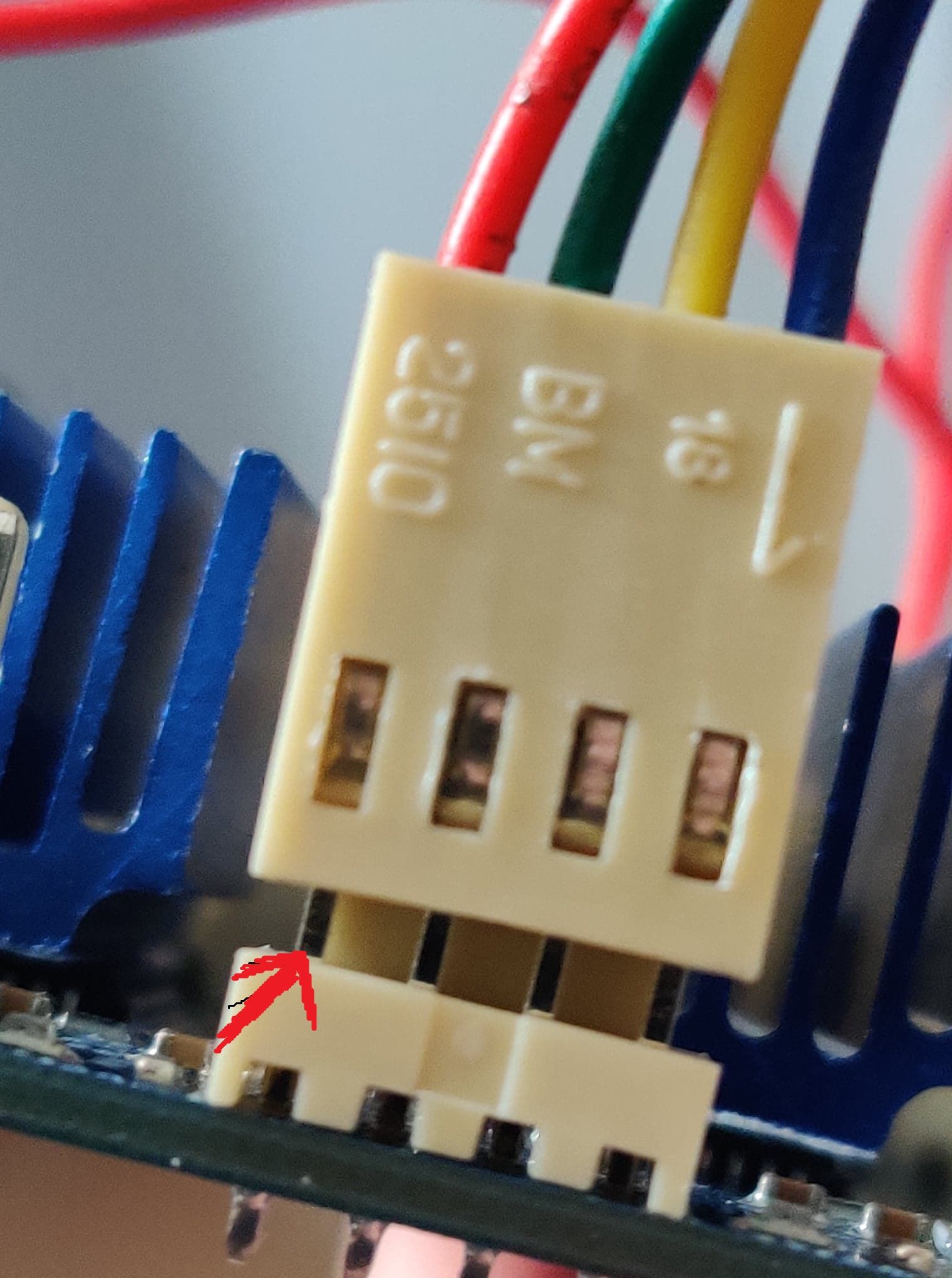
@droftarts Yeah I've checked continuity on all the wires I've even checked continuity by pulling the header up slightly and checking one end of the wire to the bottom of the pin. See image for example, red arrow where multi meter touches. And all wires have continuity so I can see how there can be any continuity issues. And I have checked the phases of all pairs and they read 2.0 ohms on all pairs.
-
@Odin Those stepper motor crimps look odd; are you sure they're not in the housing the wrong way around? Won't measuring continuity at that point just show the continuity through the stepper driver chip? Check by measuring resistance of pins without stepper motor connected.
Also, looks like you've got a clone Duet board there, with the heatsinks on the stepper driver chips. The heatsinks are quite ineffective, as the stepper driver sinks the heat through the bottom of the chip into the board. You're better off fitting a fan, pointing at the bottom side of the board, to cool it. Where did you buy the board?
Ian
Bed-slinger - Mini5+ WiFi/1LC | RRP Fisher v1 - D2 WiFi | Polargraph - D2 WiFi | TronXY X5S - 6HC/Roto | CNC router - 6HC | Tractus3D T1250 - D2 Eth
-
@droftarts I actually have two boards, Bought a clone a year ago but didnt have much success with it so went with an original a few months ago plonked the heat sinks on because thats what I had before, bought it from e3d or oozenet I remeber looking at it on both cant remember who i bought from, I can pull up the purchase emails if its important.
And sorry I have been measuring the resistance apologies for the confusion. I do agree the crimps look odd but they are definitely in the correct way -
@Odin has the board ever worked correctly? If so, how was it set up before, and what have you changed?
Ian
Bed-slinger - Mini5+ WiFi/1LC | RRP Fisher v1 - D2 WiFi | Polargraph - D2 WiFi | TronXY X5S - 6HC/Roto | CNC router - 6HC | Tractus3D T1250 - D2 Eth
-
@droftarts
Yeah it used to work fine, I had an issue with the wifi (unable to connect a few days ago) that turned out to be my wifi router causing the issue. But in the process of doing that I updated from version 3.0 of the firmware to the latest version. I also updated the wifi firmware. I have tried going back to 3.0 with no luck so I came back to the lates version, do you think its work going back to 3.0 again? -
@droftarts
I believe I have fixed the issue. I spoke to my boss who is an electrical engineer by degree and he suggested it might be a lack of voltage/current going to the board. Anyway long story short I have re stripped my V in and hey presto everything is working fine.
Thanks for the help -
@Odin Great, glad it's working. PSU was on my list as one of the next things to investigate! Though your M122 report showed 12V working fine.
Supply voltage: min 12.1, current 12.1, max 12.2, under voltage events: 0, over voltage events: 0, power good: yes
Might be worth changing to 24V if the motors are bigger. Also, it's best to use ferrules on the ends of your VIN wires, for better contact and hold in the screw gates, rather than just bare wires.
Ian
