Have our slicers been wrong this whole time?
-
@bot said in Have our slicers been wrong this whole time?:
The feature you are talking about is directly coupled to layer height, so...
In what way is accuracy coupled to layer height?
I think you are conflating accuracy and resolution.
-
Well, you lose the ability to maintain accuracy depending on what way you measure accuracy.
I presume you're speaking about X/Y size. What about the profile of the part in other dimensions? Z? Well, it can only be accurate, rounded exactly to a layer height. So, that's one basic way that we (potentially) lose accuracy. You could add on as many different sized layers on top to correct that. Fine. Z is now "accurate."
What if you have to print a slope? How shallow is that slope? If you measure the part in any way other than pure X/Y measurements, is it no longer talking about accuracy?
Are we sitting here printing calibration cubes all day? Not me. I print elaborate, detailed, complex parts that take days to complete.
Accuracy is not fudging the numbers by 8 microns to try and move the edge of a tiny rounded piece of plastic that is 40 microns tall inwards. Accuracy is making a part that matches as closely to cad as is possible.
-
@bot said in Have our slicers been wrong this whole time?:
I presume you're speaking about X/Y size.
No. I'm taking about the width of the extrusion. Its accuracy is fundamental.
But anyway.
You describe Slic3r as doing this:
fudging the numbers by 8 microns to try and move the edge of a tiny rounded piece of plastic that is 40 microns tall inwards.
You also describe Slic3r as producing dimensionally accurate parts, that if sanded down, are then undersized.
Accuracy absolutely is moving a tool path to produce the correct results.
It sounds like Slic3r does a better job than most at it.Accuracy is making a part that matches as closely to cad as is possible.
Perhaps.
In the real world we deal with DFM and all the wonderful limits of the tools we use to actually make the real object.And possible is doing a lot of heavy lifting in that sentence.

-

-
@Phaedrux said in Have our slicers been wrong this whole time?:
I never understood this received wisdom and it doesn't match my own testing. 1.2x nozzle diameter seems pretty arbitrary. Does that apply to all nozzle sizes? So my 0.6 should be 0.72 extrusion width? What if I have a 1.2mm nozzle. I should use 1.44mm width? It doesn't seem to scale well with nozzle size. What about nozzle geometry, flat or pointy?
That number works nice for "often used" nozzles, 0.25 - 0.8mm pretty good. With larger nozzle orifices it can change but for e.g. the 1.8mm nozzle and ABS and I measured even bigger 1.25-1.3 value!!! What it came from is just a whole bunch of measurements across different filaments and different nozzles. Outside nozzle geometry (flat vs pointy) does not matter much for this, only the inside geometry that affects the turbulence and nozzle material.
The "real" "safe" width should actually be measured for the nozzle, for the specific material. Rather simple, get your nozzle 4-5cm from the bed. 4-5cm is chosen as it's long enough for filament to be straight and short enough that weight of the filament does not affect it too much and extrude at extrusion speed you plan to print at till you start having filament coil on the bed. Stop extruding, let it cool, snip the filament at the nozzle and measure the diameter of the extruded filament at few points on the straight ~4cm piece of the filament. Average measured value is your "safe extrusion width".
Min is super hard to measure, I did not find a proper way to do it. In theory you should do 2 lines one after another stretching the filament with a short pause at the connection point. The connection point between two lines will have a "hole" if the filament is "over stretched" as you "pulled the filament from the nozzle" instead of pushing filament trough the nozzle. Unfortunately I never devised a test for this that I like.
Max is easy
 and it depends mostly on the outside geometry of the nozzle (pointy vs flat), flatter the nozzle wider you can go. Test is simple and it basically comes to an outside diameter of the nozzle tip (bit smaller).
But in some average value, 1.2 works nice for PLA and ABS for most of the popular nozzles (jhead, makergear, e3d.. 0.25-0.8mm). Other plastics require different numbers, for e.g. PP goes over 1.5 for the same nozzles... and for other nozzles, the value can be lesser, for e.g. the experimental Arcol nozzles where the exit channel is longer than 5x orifice diameter the value is 1.0 as there's almost no turbulence and the material do not swell at all when it exits the nozzle. Problem is extruding trough that nozzle requires 2-3x more torque

-
@bot
The one on the left.Given identical surface roughness (which you have), measuring on the line you drew, the one on the right would be oversize, one on the left would be the exact dimension.
Now, if you wanted the part oversize because you planned on finishing the surface to reduce the surface roughness, then that's a different thing. But the one on the left is closer to final dimensions of the part.
Slicing engines are trying to reproduce the CAD model, if you are going to do additional finishing, you have to plan for that.
-
@theruttmeister said in Have our slicers been wrong this whole time?:
Explain what you mean by 'discrete extrusion'?
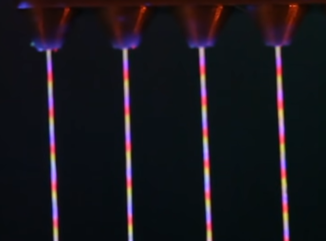
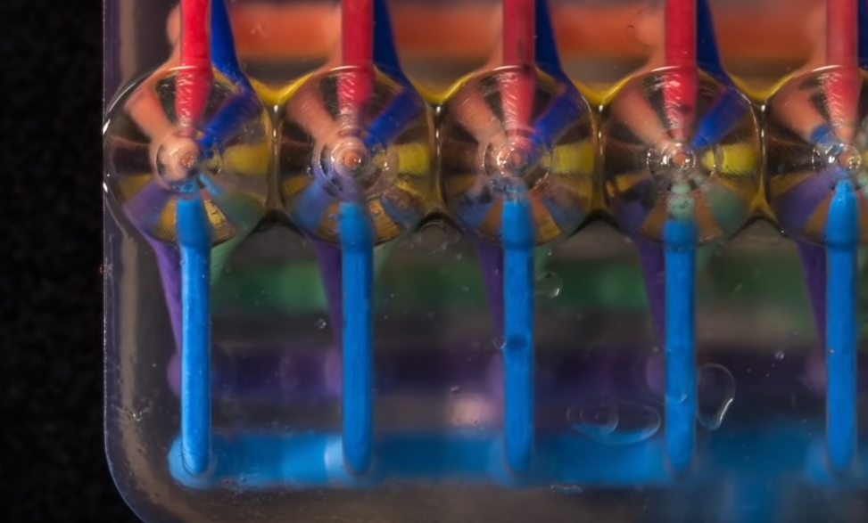
Look at the ink-jet printer, it is expelling discrete values of ink. If you look at the "bonder" printers they expel the discrete values of the bonding material (or activator, water .. irrelevant). Lool at the beeswax printers made with Epson print heads, they build 3D object out of discrete drops of vax.
check this out: https://youtu.be/2WL4b03Tfjg


None of it is plastic at the moment, but all of it represents printing with discrete, known volume "droplets". Unless we get that with plastic there will be no precision. The only other way is like some of hte "big boys" work and that's
- locked head
- locked extruder
- locked plasic
so you can use only parts provided by them, you can use plastic code 1, or code 7 etc.. and the machine & slicer know exactly how codeX pass trough the system... but if you want to use "any plastic" you are back to square one.
The current 4 axis model that everyone uses is as far as I understand any possible meaning of the word, a discrete extrusion model. One where the volume of extrusion is controlled directly and independently of factors like feed rate.
yeah, but it's NOT

if it was then you would not need pressure advance, retraction, priming, coasting, wiping and all the other crap we try to use to compensate for the fact that it's not
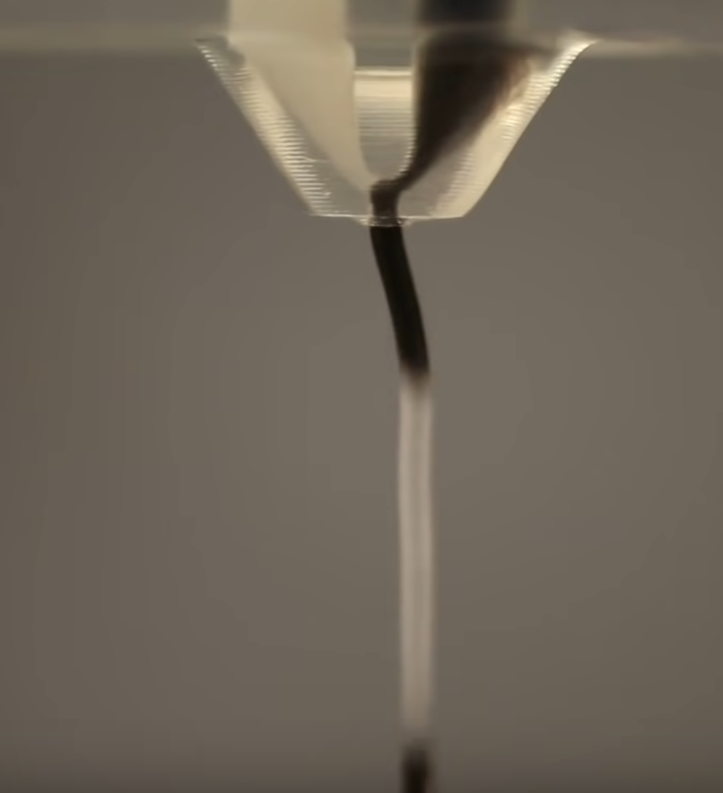
The Voltera is dealing with a wildly different rheology problem, given that they are pushing a non-Newtonian fluid at room temperature, using a piston, through a very different nozzle.
yes and no, but that's out of the point, the point I made with Voltera is just that making adequate model is obviously possible, on the other hand it probbly requires locked parts (including plastic)
-
@bot said in Have our slicers been wrong this whole time?:
On top of that, stock slic3r simplifies toolpaths excessively. Accuracy thrown out the window again.
There was always a tradeoff there... The first slicers I used were something dr. Adrian made and skeinforge. Both worked by creating a slice of the object and generating a bitmap of that slice at some resolution, then they would vectorize this bitmap and generate g-code from those vectors. It's a super slow process but worked rather good with non manifold parts and parts with different errors. First slicer that actually generated proper vectors by intersecting a plane and the stl was netfabb and what happened is that slicing became 1000+ times faster but they had issue with non-perfect objects (luckily netfabb is also awesome to fix the STL so that was not a problem) and with "too precise" objects as by deciding on the resolution of the bitmap skeinforge could define shortest move, netfabb had to implement additional "optimizer" on top of that to now "fix all the short moves"... same issue was later on with all the other slicers doing the similar thing, IIRC s3d solved this partially with 3.0 and finally with 3.1, before 3.0 they would generate a G1 for every nanometer you had in your STL... slic3r had the optimization from start IIRC, no clue how it's implemented... but you can't go around that, you can just make it configurable so user can decide how this simplification works...
What's bigger issue and huge difference between slicers is the optimization of generated G-code. Last time I compared S3D and Cura, S3D code was way better, more optimized, cura generated code was jumping all over the place... dunno if this changed, have not checked cura for a while.
-
@bot said in Have our slicers been wrong this whole time?:
S3D is by far the worst slicer I've analysed in terms of extrusion rate consistency.
They also simplify their toolpaths now, too.Try to get version before 3.0
 and test it out, 3.0 is when they introduced simplification of toolpaths
-
@bot said in Have our slicers been wrong this whole time?:

I would actually love if a slicer would ASK me if I want the left or the right one
 ... and I know that in 90% cases I would want the left one for inside of the object (holes) and right one for the outside of the object
-
@arhi I remember very well. I used to take full advantage of the non-excessively simplified toolpaths!
@arhi said in Have our slicers been wrong this whole time?:
[...]
I would actually love if a slicer would ASK me if I want the left or the right one ... and I know that in 90% cases I would want the left one for inside of the object (holes) and right one for the outside of the object
Now that's truly a good idea.
-
@arhi said in Have our slicers been wrong this whole time?:
@theruttmeister said in Have our slicers been wrong this whole time?:
Explain what you mean by 'discrete extrusion'?
Look at the ink-jet printer, it is expelling discrete values of ink. If you look at the "bonder" printers they expel the discrete values of the bonding material (or activator, water .. irrelevant). Lool at the beeswax printers made with Epson print heads, they build 3D object out of discrete drops of vax.
I'm very much familiar with jetting technology...
Jetting is able to deposit finer volumes... but no existing tech is capable of functioning at 200C+ as is required for thermoplastics, let alone deal with the far far higher viscosity of molten thermoplastics.4 Axis FDM is able to deposit finely controlled, discrete volumes of polymer...
With more control than most jetting tech as it is able to vary the velocity of its deposition (Jetting typically cannot). In fact, the ability to deposit truly continuous beads of polymer is a huge advantage of FDM vs Jetting.Or do you mean droplets? Because droplet thermoplastic printing, well... both not currently practical and not actually desirable (due to its impacts on mechanical strength). Oh and droplet based means 100% infill 100% of the time, and support material for even 1 degree of overhang.
I mean if you can figure out how to build a head with 42,000 nozzles that can jet out PLA, woo hoo!
But HP went with MJF for a reason. -
@bot said in Have our slicers been wrong this whole time?:
@arhi I remember very well. I used to take full advantage of the non-excessively simplified toolpaths!
there might be a way to control how much they are simplified ... but I gave up on s3d so don't remember if there's a "precision" settings there.
with IM this is more than enough for me

-
Yes. X/Y compensation for the print achieves the same thing, while allowing the flow and width of the extrusions to remain as specified by the user. PrusaSlicer even has this feature! So the flow math is redundant.
I played around with the IM simplification for a tiny bit -- it seems they have a hard minimum that is coarser than I'd prefer.
-
@bot said in Have our slicers been wrong this whole time?:
Yes. X/Y compensation for the print achieves the same thing, while allowing the flow and width of the extrusions to remain as specified by the user. PrusaSlicer even has this feature! So the flow math is redundant.
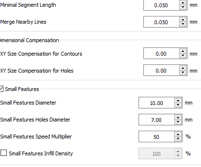
I was more thinking about min seg leng. and merge nearby lines wrt optimization
 .. but added compensation and small features as those three groups together solve most of my accuracy problems
 -
@arhi I caught that after I replied

-
@theruttmeister said in Have our slicers been wrong this whole time?:
@bot
The one on the left.Given identical surface roughness (which you have), measuring on the line you drew, the one on the right would be oversize, one on the left would be the exact dimension.
Now, if you wanted the part oversize because you planned on finishing the surface to reduce the surface roughness, then that's a different thing. But the one on the left is closer to final dimensions of the part.
Slicing engines are trying to reproduce the CAD model, if you are going to do additional finishing, you have to plan for that.
That's not quite how it works. You don't get to choose the precise spot you take a measurement. You have to assume that the measuring tool will as likely fall in a void as it will land on that tiny bump that defines the external nominal profile.
-
@theruttmeister said in Have our slicers been wrong this whole time?:
I'm very much familiar with jetting technology...
I'm just a user there, outside of my aria of interest
4 Axis FDM is able to deposit finely controlled, discrete volumes of polymer...
With more control than most jetting tech as it is able to vary the velocity of its deposition (Jetting typically cannot). In fact, the ability to deposit truly continuous beads of polymer is a huge advantage of FDM vs Jetting.I disagree but hey, we can't agree on everything :D.
Why I disagree
-
when you start extruding there is an unknown time delay before plastic start exiting. This time delay depends on many factors and is mostly ignored by the slicers. Effects of this problem are "hidden" by "prime nozzle" parameter, pressure advance...
-
when you stop extruding there is and unknown time delay before plastic stop extruding and to add to that plastic does not exit at same speed during this "stop" time. Effects of this problem are "hidden" by "retraction", pressure advance, coasting, wiping...
So IMHO we cannot deposit "finely controlled, discrete volumes of polymer", we deposit something "close to it" and then hide the effects of the error.
Or do you mean droplets?
No, not really, I mean, some way of having discrete deposition possibility. No clue how, if I had an idea I'd come out with it :). Looking at this weird view of the printer I mentioned

maybe some rotating drum with holes "accepting" a known discrete volume of molten plastic sending it further down the path
 ...
... -
-
@bot said
That's not quite how it works. You don't get to choose the precise spot you take a measurement. You have to assume that the measuring tool will as likely fall in a void as it will land on that tiny bump that defines the external nominal profile.
You don't measure with a device of zero width. Any measurement is of the highest points that are contacting your tool.
Hence surface roughness being relevant.The line you drew is exactly how you would measure those surfaces.
-
Ah, I see you like to throw out accuracy when measuring, too. A caliper is not always the right tool for the job.
It seems we will have to agree to disagree here, and maybe get back to the intended topic at hand.