Possible PWM port issue & RRF3 Question
-
@jallen810 said in Possible PWM port issue & RRF3 Question:
When i put a metal object under it, the reading drops to ~20.
I think that would be the inversion, so you'd need the ! in the pin name.
You might also need the pullup resistor enabled by adding a
^to the pin nameM558 P5 C"!^zprobe.in" H5 F600 T6000 -
@Phaedrux okay I will try that, what exactly is the application for this pull up resistor? Could it be the reason my endstops are acting funny?
It almost acts like the machine thinks it’s homes as soon as I push the home button... very weird.My homex,y,z and all fills are updated from S to H.. so that looks fine... any other ideas other than I just need to try running 24v of power to them?
-
@jallen810 A pull-up (or pull-down) resistor is a resistor used to ensure a known state for a signal. A switch should either send a 3.3V, or be connected to GND (0V), but some switches 'float' and give a partial voltage, which can lead to unexpected triggering. A pull up resistor will make sure that voltage is 3.3V. However, I don't think this is your issue.
Your probe:
Old RRF2 config:M558 P5 H5 F600 A1 I1The 'I1' means the probe is inverted. A1 is the number of times the probe will probe each point (1 is default). No travel speed 'T' set.
New RRF3 config:M558 P1 C"zprobe.in" H5 F600 T6000Wrong probe type, not inverted. Try:M558 P5 C"!zprobe.in" H5 F600 T6000See https://duet3d.dozuki.com/Wiki/Gcode?revisionid=HEAD#Section_M558_Set_Z_probe_type for details.
Your endstops:
Old RRF2 config:M574 X1 Y1 S0endstops on low end, S0 means active low
New RRF3 config:M574 X2 S1 P"xstop"andM574 Y2 S1 P"ystop"
Both set at wrong end (X2 and Y2 should be X1 and Y1, unless you've changed the position). S1 is fine (says it's a microswitch), but needs to be inverted. Try:M574 X1 S1 P"!xstop" M574 Y1 S1 P"!ystop"See https://duet3d.dozuki.com/Wiki/Gcode?revisionid=HEAD#Section_M574_RepRapFirmware_Num_3 and https://duet3d.dozuki.com/Wiki/Connecting_endstop_switches for details.
Ian
-
@droftarts @Phaedrux @bearer
Thank you all for your help with this upgrade to RRF3, I did finally get everything working properly again! I am running my first print now! Woot woot!One last question to you @droftarts, I figured out that I had to invert my endstop signals ~2hr before your comment but I had to do the following:
CONFIG.g
;----Endstops--------------------------------------------------------------------------------------------------------------------------------------------------------------------------
M574 X1 S1 P"!xstop"                                       ; configure active-low endstop for low end on X via pin xstop
M574 Y1 S1 P"!ystop"                                       ; configure active-low endstop for low end on Y via pin ystop
M574 Z1 S2                                                 ; configure Z-probe endstop for low end on Z
HOMEX.g
; homex.g
; called to home the X axis
;
; generated by RepRapFirmware Configuration Tool v3.1.4 on Sat Aug 15 2020 15:29:15 GMT-0400 (EDT)
G91              ; relative positioning
G1 H2 Z5 F6000   ; lift Z relative to current position
G1 H1 X-305 F1800 ; move quickly to X axis endstop and stop there (first pass) 305
G1 H2 X5 F6000  ; go back a few mm
G1 H1 X-305 F360  ; move slowly to X axis endstop once more (second pass)
G1 H2 Z-5 F6000  ; lower Z again
G90              ; absolute positioning
HOMEY.g
; homey.g
; called to home the Y axis
;
; generated by RepRapFirmware Configuration Tool v3.1.4 on Sat Aug 15 2020 15:29:15 GMT-0400 (EDT)
G91              ; relative positioning
G1 H2 Z5 F6000   ; lift Z relative to current position
G1 H1 Y-340 F1800 ; move quickly to Y axis endstop and stop there (first pass)
G1 H2 Y-5 F6000  ; go back a few mm
G1 H1 Y-340 F360  ; move slowly to Y axis endstop once more (second pass)
G1 H2 Z-5 F6000  ; lower Z again
G90              ; absolute positioning
Question is: Why did I have to switch my "home" coordinate for both X&Y from 305/340 to -305/-340 when I switched to RRF?
-
@jallen810 said in Possible PWM port issue & RRF3 Question:
Question is: Why did I have to switch my "home" coordinate for both X&Y from 305/340 to -305/-340 when I switched to RRF?
The question is, where are your endstops?
For X if its on the left side, it's at the low end and moves to the endstop would be negative.
For Y, if it's at the front, it's at the low end and moves to the endstop would be negative. And vice versa.
-
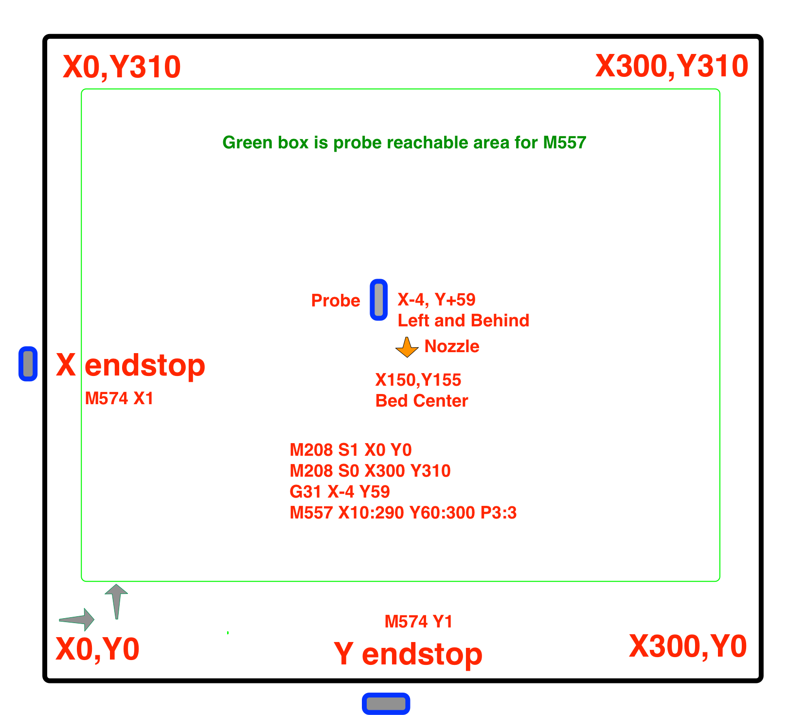
@Phaedrux here is how my bed is oriented, mind you, the code i placed above works as this diagram shows, it just doesn't make sense that is it not exactly the same as my RRF2.x was. It would seem that should not change from one to the next.
[Lastly, note i need to update my M557, i just noticed a typo when i was making this diagram") ]
]
-
@jallen810 You have a max Y endstop, and a minimum X endstop. Also, your drive direction assignments (S parameter in M569) are all different between your RRF2 and RRF3 configs:
RRF2;-----Drives----------------------------------------------------------------------------------------------------------------------------- M569 P0 S0 D2 ; (X-Axis) drive 0 goes forwards (Jake wrong config M569 P0 S1) M569 P1 S1 D2 ; (Y-Axis) drive 1 goes forwards M569 P2 S1 D2 ; (Z-Axis) drive 2 goes forwards M569 P3 S1 D2 ; (Extruder) drive 3 goes backward with Bondtech (titan = S0, Bondtech = S1)RRF3
; Drives
M569 P0 S1                                                ; physical drive 0 goes forwards
M569 P1 S0                                                ; physical drive 1 goes backwards
M569 P2 S0                                                ; physical drive 2 goes backwards
M569 P3 S0                                                ; physical drive 3 goes backwards
So I think you have some additional sorting out to do, and that nothing has changed in behaviour between RRF2 and RRF3 in this respect. I think your RRF2 config was just wrong!
First, get your drives going the right way, by testing a +ve X move sends the nozzle to the right, and a +ve Y move sends the nozzle towards the back of the bed.
Then get the endstop settings correct. Should be:
M574 X1 S1 P"!xstop"
M574 Y2 S1 P"!ystop"
Lastly, your homeall.g and homey.g should change so that the large Y move is positive; the large X should stay negative. eg:
G91              ; relative positioning
G1 H2 Z5 F6000   ; lift Z relative to current position
G1 H1 Y340 F1800 ; move quickly to Y axis endstop and stop there (first pass)
G1 H2 Y-5 F6000  ; go back a few mm
G1 H1 Y340 F360  ; move slowly to Y axis endstop once more (second pass)
G1 H2 Z-5 F6000  ; lower Z again
G90              ; absolute positioning
Ian
-
@jallen810 said in Possible PWM port issue & RRF3 Question:
here is how my bed is oriented, mind y
be careful of your slicer settings if you deviate from the normal cartesian layout shown by Phaedrux , you could easily end up with parts mirrored along one or more axes.
-
I just wrote a post in another thread that seems applicable here.
https://forum.duet3d.com/topic/18241/duet-2-wifi-bltouch-issues-on-ender-5-pro/37?_=1597982074306
-
@Phaedrux @bearer @droftarts all very good links, i think that clears up the concept for me so i understand what i did wrong. I will investigate and test everything this weekend. I'm happy this re-wire is finally complete. I can finally get back to printing
")