Controller for my larg format 3D printer
-
there are currently some limitations
see
https://duet3d.dozuki.com/Wiki/Duet_3_firmware_configuration_limitationsFilament monitors for extruders driven by expansion boards and tool boards are not yet supported. Support is planned in release 3.3.0. The filament monitor will need to be connected to the board driving the corresponding extruder.
A heater on an expansion or tool board can only be controlled by a temperature sensor on the same expansion board.
-
As @Veti says, the thermistors for the extruders should be connected to the expansion board. Support for filament monitors for extruders connected to expansion and tool boards is one of our highest priorities, and I expect to start work on that for the 3.3 release even before 3.2 stable is released.
If your extruders are direct drive and have modest motor current requirement, you may wish to consider using three tool boards instead of one 3-channel expansion board, because it will simplify the wiring to the tool heads.
For maximum fail-safeness, I suggest you connect the emergency stop button to the main board if possible.
You have only shown one fan per extruder. Do you not have print cooling fans as well as heatsink fans?
Duet WiFi hardware designer and firmware engineer
Please do not ask me for Duet support via PM or email, use the forum
http://www.escher3d.com, https://miscsolutions.wordpress.com -
Right now, my top priority is to get the car moving in the best way.
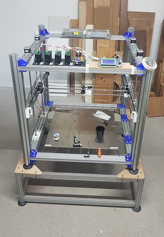
In the prototype that I have already assembled (and which "moves" with Arduino + Ramps), several components are still missing, such as the heated bed or the walls of the room.
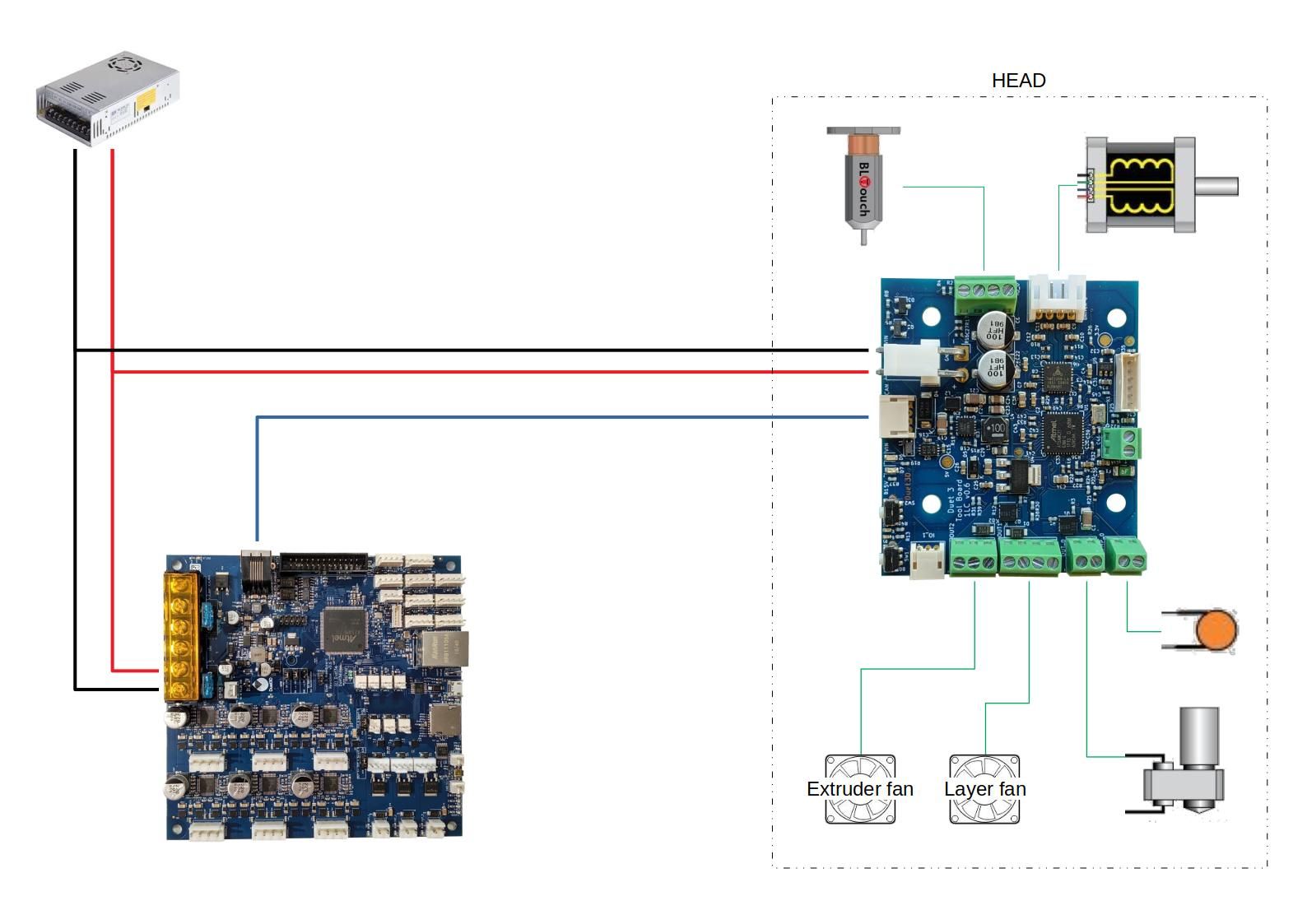
In addition, only 1 extruder will be mounted for the moment.In the diagram I tried to insert everything that came to my mind and that concerns the prototype in the 3D printer version.
In reality the head, in the final version, will have 2 extruders or a laser diode or a small cutter for soft materials. But they are still ideas for later versions.At the moment I am interested in being able to move the printer with the self-leveling and MK8 extruder that I have on the old printer. The rest will come calmly and in the future!
Consequently, I can connect the hot end directly to the mainboard by eliminating some pieces that are not needed at the moment.
-
@dc42 said in Controller for my larg format 3D printer:
As @Veti says, the thermistors for the extruders should be connected to the expansion board. Support for filament monitors for extruders connected to expansion and tool boards is one of our highest priorities, and I expect to start work on that for the 3.3 release even before 3.2 stable is released.
we have time to do everything!
If your extruders are direct drive and have modest motor current requirement, you may wish to consider using three tool boards instead of one 3-channel expansion board, because it will simplify the wiring to the tool heads.
I am not an expert in this electronics (until now I have only made CNC with breackout board, driver and linuxCNC) and that is why I asked for information.
I am making this machine for myself, but I would like to put a larger version of it on the market. I am open to any suggestions and / or collaboration ... because I think the project is interesting!For maximum fail-safeness, I suggest you connect the emergency stop button to the main board if possible.
Yes, No problem
You have only shown one fan per extruder. Do you not have print cooling fans as well as heatsink fans?
I forgot about it
-
To clarify the point about tool boards:
-
If the extruders will be direct drive, then for each extruder you are likely to have 4 motor wires, 4 fan wires, 2 heater wires, 2 thermistor wires. That's 12 wires going to the hot end assembly (with the possibility of reducing it to 10 if you share the V+ wires to the heater and fans). if you want to add a BTouch, that's 4 more wires. if you want to use fans with tachos, even more wires.
-
A direct drive extruder with a tool board mounted on the extruder assembly needs just power and ground, plus 4 CAN wires (which can be reduced to 2 if the wires are not too long). That's even if you use fans with tachos and a BLTouch. For the case of a single extruder, it also costs less, even if you include a tool distribution board to make future expansion easier.
-
If the extruders are not direct drive, then it's probably simpler to use the 3-channel expansion board instead.
Think of an tool board as a single-channel expansion board, small enough to be mounted on the tool head, and with lower maximum motor current than the 3-channel expansion board.
Duet WiFi hardware designer and firmware engineer
Please do not ask me for Duet support via PM or email, use the forum
http://www.escher3d.com, https://miscsolutions.wordpress.com -
-
how long is "not too long"? 750mm? 500mm? "Depends"?
<>RatRig V-Minion Fly Super5Pro RRF<> V-Core 3.1 IDEX k*****r <> RatRig V-Minion SKR 2 Marlin<>
-
@oliof said in Controller for my larg format 3D printer:
how long is "not too long"? 750mm? 500mm? "Depends"?
I suspect that 1m would be OK. Ideally, ferrite beads would be added at one end of the cable, to reduce reflections.
-
The "small" (this one) has a useful print volume of 600x600x600mm expandable up to 1200x1200x1200 with Nema17 motors. The moment of the X and Y axes is a toothed belt with recirculating ball guides. Z axis with recirculating ball screws and recirculating ball guides.
The "large" version uses Nema23 motors instead and will have useful dimensions of 1000x1000x1000 mm expandable up to 3000x3000x3000 mm. The movement of the X and Y axes is by rack with linear encoder. Z axis with recirculating ball screws and recirculating ball guides.@oliof
this projectMy prototype (pictured) uses structural and mechanical parts recovered from old CNCs and 3D printers and has a useful volume of 600x600x600mm.
-
-
yes that is the one
-
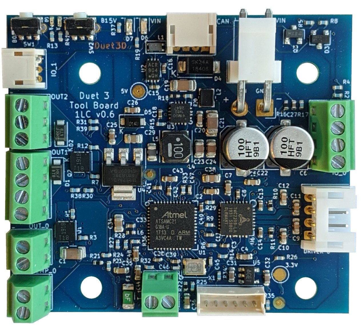
More info on the tool board at https://duet3d.dozuki.com/Wiki/Duet_3_Tool_Board.
Duet WiFi hardware designer and firmware engineer
Please do not ask me for Duet support via PM or email, use the forum
http://www.escher3d.com, https://miscsolutions.wordpress.com -
-
Hello to you, fellow large format printer maker
")
@bernardomattiucci said in Controller for my larg format 3D printer:
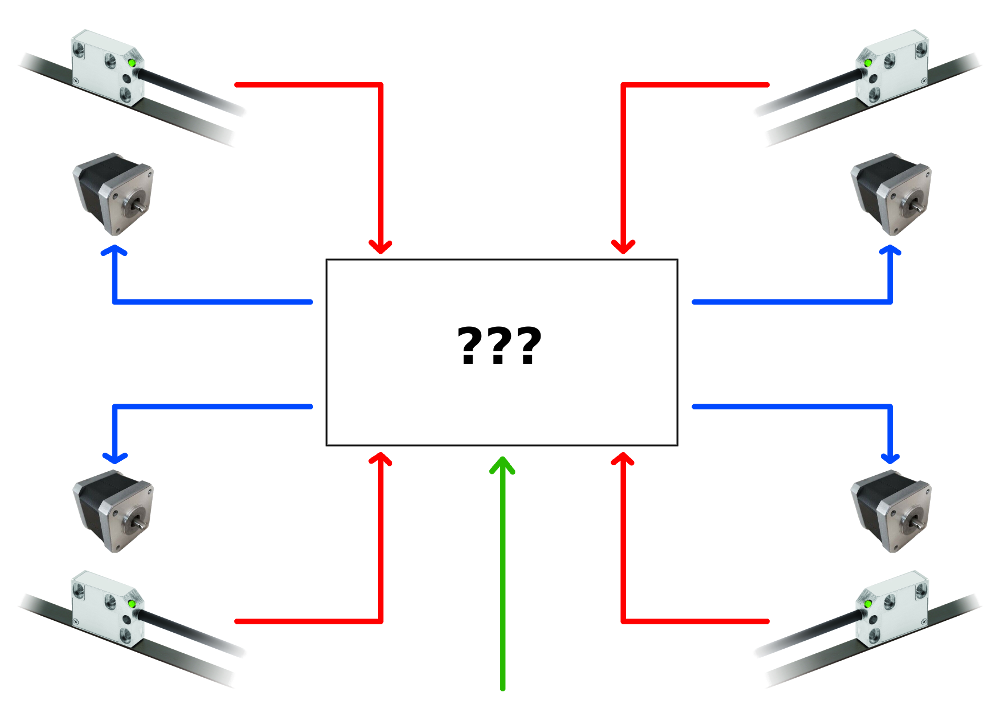
This plan should be calibrated every time the Z axis is zeroed, to do this I thought of controlling the 4 motors independently and using the (optical) limit switches, 1 for each motor, in order to have a fixed reference for each edge of the XY plane.
Instead of this, I'd suggest you to use only one limit switch at the top of one of your Z axis corner and install a BL touch or any other probe you like somewhere on your tool head.
The printer will first go to its home position, moving until it hits the endstop. Then it will go down until the Z probe hits the bed. Next step will be to probe each corner, near your leadscrews. After that, the printer will adjust the bed to make it leveled automatically.
I only have 2 Z axis on my printer but that's how I did it, same principle for you there with 4 axis. It's much easier to do it this way.
-
Thanks for the suggestion, very interesting!
-
Ok
If I am not mistaken, then, I should take the following:1 Duet 3 Mainboard 6HC +
1 Duet Toolboard +
1 Duet PanelDue 7" +
1 BLTouchCorrect?
-
@bernardomattiucci said in Controller for my larg format 3D printer:
1 Duet Toolboard +
if you want 3 extruders, then you need 3 toolboards or 1 Duet_3_Expansion_board_3HC
-
-
You might also want to buy a Tool Distribution board. You can manage without it, but it make wiring easier when you add more extruders. If you don't use one, you will need add a CAN termination resistor, and provide a fuse in the VIN feed to the tool board. See https://duet3d.dozuki.com/Wiki/Duet_3_Tool_Board#Section_Connecting_CAN_FD_Bus_and_Power.
-
Good morning,
is there the possibility of having the 4 motors of the Z axis of the "closed loop" type with 4 linear encoders mounted on the recirculating ball guides placed at the 4 edges of the XY plane?
-
Not yet, but we have a closed loop expansion board for Duet 3 under development.