Giant Delta printer Slow Homing issue.
-
@Phaedrux said in Giant Delta printer Slow Homing issue.:
Well if you're certain that tooth to tooth distance is 10mm then I guess that's that.
I have confirmed twice also in the video once, step/mm calculation is right according to the 10 mm pitch.
The Actual problem is on the last axis homing.
I will try to setup like a cartesian machine and try homing again. -
Please can you show in a video how you measured the tooth pitch to be 10mm.
-
@sozkan said in Giant Delta printer Slow Homing issue.:
@Phaedrux said in Giant Delta printer Slow Homing issue.:
Well if you're certain that tooth to tooth distance is 10mm then I guess that's that.
I have confirmed twice also in the video once, step/mm calculation is right according to the 10 mm pitch.
The Actual problem is on the last axis homing.
I will try to setup like a cartesian machine and try homing again.can you also move the 50mm like you did set your callipers to that and then show us the callipers against the belt teeth if you move 50 mm then we should only see 5 teeth if the belts are truly 10 mm pitch (Which I doubt)
-
as you can see we are all very interested, as we have not seen a belt like that
")
the white belts tend to have steel cores. they tend to break especially with 180 degree turns.
can you please post a link to the belts used. -
@Dougal1957
Hi, here is the link of the video of breef info about components and measurement proof of belt teeth .
Youtube Link: for the homing calibration and teeth -
This post is deleted! -
@Veti said in Giant Delta printer Slow Homing issue.:
as you can see we are all very interested, as we have not seen a belt like that
the white belts tend to have steel cores. they tend to break especially with 180 degree turns.
can you please post a link to the belts used.First of all thanks for the concern. There is steel fiber, the Smaller the pulley, the lesser the life span. But 14 teeth hopefully not a big problem.
Here is the link information about belt : Belt info: https://www.maedler.de/Article/16470000 -
Thanks for confirming the belt pitch; I am sorry that I doubted you.
@sozkan said in Giant Delta printer Slow Homing issue.:
I have changed as you suggested it did not work!
working one as previous :; Drives M569 P0 S1 R1 T3:3:5:0 ; physical drive 0 goes Forward M569 P1 S1 R1 T3:3:5:0 ; physical drive 1 goes Forward M569 P2 S1 R1 T3:3:5:0 ; physical drive 2 goes Forward M569 P3 S1 R1 T3:3:5:0 ; physical drive 3 goes Forward M584 X6 Y7 Z8 E5 ; set drive mappingThose M569 commands are definitely wrong. Your external drivers are P5 P6 P7 P8 as @jay_s_uk said. This is probably why the motors move the correct amount when all 3 are moving, but not when just one is moving. That in turn explains the slow down when one carriage reaches the endstop, and the failure to complete homing (because the other carriages are not travelling as far as they should).
Duet WiFi hardware designer and firmware engineer
Please do not ask me for Duet support via PM or email, use the forum
http://www.escher3d.com, https://miscsolutions.wordpress.com -
@dc42 said in Giant Delta printer Slow Homing issue.:
P5 P6 P7 P8
Hi, Thank you for concerning and valuable input.
I have changed again M569 values as you mentioned. Motor did not moved. But they became motors off stage. I mean motor enable signal reversed, So motors free while homing but none of them moving.
here is the current code : Do I need to change any other code relative to the Drive P values?; Drives M569 P5 S1 R1 T3:3:5:0 ; Extruder drive 0 goes Forward M569 P6 S1 R1 T3:3:5:0 ; X:A drive 1 goes Forward M569 P7 S1 R1 T3:3:5:0 ; Y:B drive 2 goes Forward M569 P8 S1 R1 T3:3:5:0 ; Z:C physical drive 3 goes Forward M584 X6 Y7 Z8 E5 ; set drive mappingDid I miss anything ? I am going to reverse Drivers Enable signal input right now for try. I wonder if that one is the problem.
Thanks. -
That's a good sign as it means your drivers are actually being set by the firmware now.
You can change whether the motors are active high or active low using the R value. So it seems you need them all on active low. Change R1 to R0 on each driver -
@jay_s_uk said in Giant Delta printer Slow Homing issue.:
That's a good sign as it means your drivers are actually being set by the firmware now.
You can change whether the motors are active high or active low using the R value. So it seems you need them all on active low. Change R1 to R0 on each driverWith previously updated values, I have reversed enable cables on driver that makes the motors move with a horrible sound like noisy signals and slow all axis. I will test now with R0 and also revert the enable cable inputs for a try.
-
@sozkan what external boards are you using? do you have a link?
-
@jay_s_uk said in Giant Delta printer Slow Homing issue.:
@sozkan what external boards are you using? do you have a link?
It seems right this time but with this "P5, P6, P7, P8" values all motors running with noisy signals and slower with vibration. Homing not successful at first. Distancing not correct.
Driver : https://www.act-motor.com/closed-loop-stepper-driver-hbs86h.html
Motor : Motor and Driver Set -
looking at the datasheet I think your timing are not correct for the driver.
there needs to be at least a 6us setup time for direction
I would maybe try a timing of T3:3:6:0 -
Looking at the data fore the driver that you linked to, the other thing you may need to do is use the alternate connection method to the expansion board:
- Connect PUL+ and DIR+ driver input to the +5V pin on one of the servo headers on the breakout board
- Connect PUL- to STEP- on the breakout board, and DIR- to DIR-.
The data says that you can leave ENA+ and ENA- not connected. This is probably best until you get everything working, however the Duet won't be able to turn the motors off. Therefore, when movement is working correctly, you may wish to connect ENA+ to +5V on the breakout board, and ENA- to ENA-. Use whichever of R0 and R1 works in the M569 commands.
-
Hi,
It finally succeeds, running smooth and correct in calibration, homing perfect, by changing ;- Connect PUL+ and DIR+ driver input to the +5V pin on one of the servo headers on the breakout board
- Keep Remain PUL- to STEP- on the breakout board, and DIR- to DIR-.
- Revert back the P values to "P0, P1, P2, P3" ( Because Correct one Create noise like ball bearings broken and move uncalibrated ). Therefore I cannot control the default direction (S values) ( But however on the drive I managed to change it ).
In a conclusion, even if it is solved, working better with an incorrect parameter. However, a +5V connections make a good job.
I still want to work with the correct parameters as you advise.
Thank you very much.
-
@sozkan said in Giant Delta printer Slow Homing issue.:
Revert back the P values to "P0, P1, P2, P3" ( Because Correct one Create noise like ball bearings broken and move uncalibrated ). Therefore I cannot control the default direction (S values) ( But however on the drive I managed to change it ).
Your external axes will be using default timing. Send
M569 P5and see what it says. It did not run well because of the T parameter settings you used:M569 P5 S1 R1 T3:3:5:0From the product page you linked, there's this, which shows the timing you should be using:
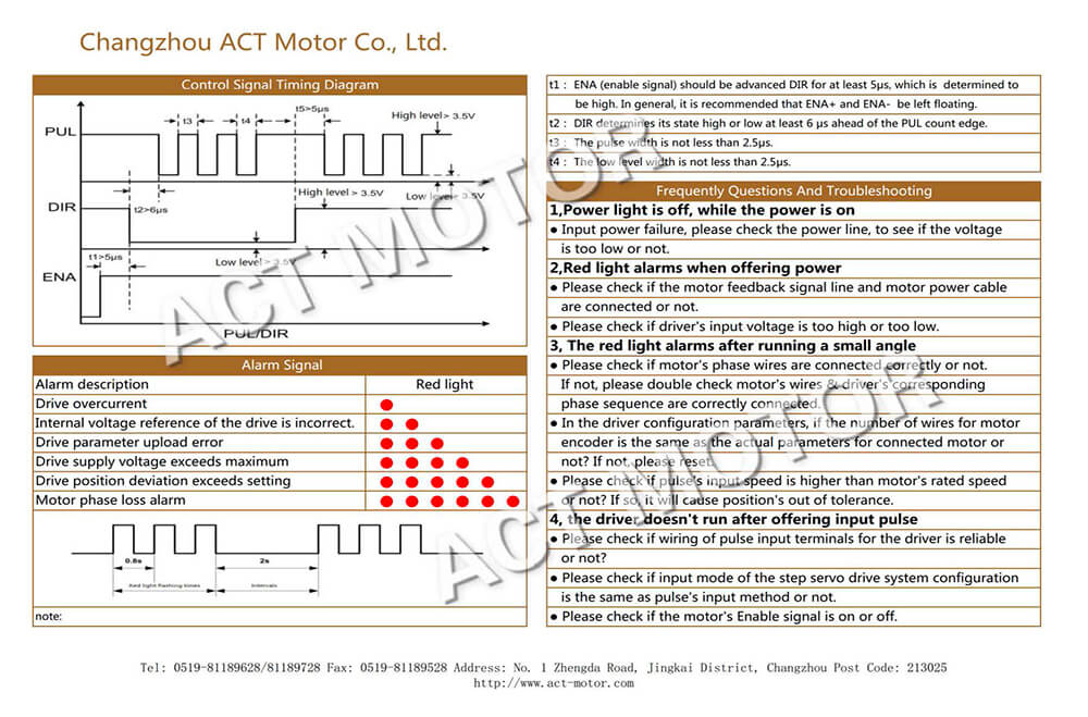
M569 T parameter, where Taa:bb:cc:dd:
aa = Minimum driver step pulse width, in microseconds = t3 in image = not less than 2.5us
bb=step pulse interval, in microseconds = t4 in image = not less than 2.5us
cc=direction setup time, in microseconds = t1/t2/t5 in image = at least 6us
dd=direction hold time, in microseconds = t1/t2/t5 = at least 6us
Enable signal t1 = assume that you have ENA+ an ENA- floating, so constantly enabled. Also, I think t3 and t4 are the wrong way around in the image, but they are the same value.From this, try:
M569 P5 S1 R1 T2.5:2.5:6:6  ; Extruder drive 0 goes Forward
M569 P6 S1 R1 T2.5:2.5:6:6  ; X:A drive 1 goes Forward
M569 P7 S1 R1 T2.5:2.5:6:6  ; Y:B drive 2 goes Forward
M569 P8 S1 R1 T2.5:2.5:6:6  ; Z:C physical drive 3 goes Forward
Ian
Bed-slinger - Mini5+ WiFi/1LC | RRP Fisher v1 - D2 WiFi | Polargraph - D2 WiFi | TronXY X5S - 6HC/Roto | CNC router - 6HC | Tractus3D T1250 - D2 Eth
-
@droftarts said in Giant Delta printer Slow Homing issue.:
@sozkan said in Giant Delta printer Slow Homing issue.:
Revert back the P values to "P0, P1, P2, P3" ( Because Correct one Create noise like ball bearings broken and move uncalibrated ). Therefore I cannot control the default direction (S values) ( But however on the drive I managed to change it ).
Your external axes will be using default timing. Send
M569 P5and see what it says. It did not run well because of the T parameter settings you used:M569 P5 S1 R1 T3:3:5:0From the product page you linked, there's this, which shows the timing you should be using:
M569 T parameter, where Taa:bb:cc:dd:
aa = Minimum driver step pulse width, in microseconds = t3 in image = not less than 2.5us
bb=step pulse interval, in microseconds = t4 in image = not less than 2.5us
cc=direction setup time, in microseconds = t1/t2/t5 in image = at least 6us
dd=direction hold time, in microseconds = t1/t2/t5 = at least 6us
Enable signal t1 = assume that you have ENA+ an ENA- floating, so constantly enabled. Also, I think t3 and t4 are the wrong way around in the image, but they are the same value.From this, try:
M569 P5 S1 R1 T2.5:2.5:6:6  ; Extruder drive 0 goes Forward
M569 P6 S1 R1 T2.5:2.5:6:6  ; X:A drive 1 goes Forward
M569 P7 S1 R1 T2.5:2.5:6:6  ; Y:B drive 2 goes Forward
M569 P8 S1 R1 T2.5:2.5:6:6  ; Z:C physical drive 3 goes Forward
Ian
Hello. Thank you for your concern and effort.
I was busy with upgrading mechanical hardware.
I just came to this point once again. The problem is not solved yet. When P values changed to 5,6,7 sounds horrible and inccorrect. But when P values 1,2,3 it is working but not correct right?
Please see the video I make on youtube : Link for video. -
In your video it looks like you're getting an error message when trying to save the config.g and reboot the board. Failed to download config.g.
Are the updates you are making to config.g actually getting saved?
Can you please provide the results of M122 and M98 P"config.g" ?
-
@Phaedrux said in Giant Delta printer Slow Homing issue.:
In your video it looks like you're getting an error message when trying to save the config.g and reboot the board. Failed to download config.g.
Are the updates you are making to config.g actually getting saved?
Can you please provide the results of M122 and M98 P"config.g" ?
Please check the full code:
; Configuration file for Duet WiFi (firmware version 3)
; executed by the firmware on start-up
;
; generated by RepRapFirmware Configuration Tool v3.1.4 on Sun Sep 27 2020 20:52:39 GMT+0200 (Central European Summer Time)

; General preferences
G90                                                ; send absolute coordinates...
M83                                                ; ...but relative extruder moves
M550 P"Giant3D"                                    ; set printer name
M665 R600 L1200 B575 H1450                         ; Set delta radius, diagonal rod length, printable radius and homed height
;M564 H0					     				   ; allow jog without homing
M666 X0 Y0 Z0                                      ; put your endstop adjustments here, or let auto calibration find them

; Network
M551 P"xxxxxx"                                ; set password
M587 S"WfiName" P"xxxxxx" I192.168.1.200
M552 S1                                            ; enable network
M586 P0 S1                                         ; enable HTTP
M586 P1 S0                                         ; disable FTP
M586 P2 S0                                         ; disable Telnet

; Drives
M569 P5 S0 R0 T3:3:5:0                                       ; Extruder drive 0 goes Forward
M569 P6 S1 R0 T2.5:2.5:6:6  ; X:A drive 1 goes Forward
M569 P7 S1 R0 T2.5:2.5:6:6  ; Y:B drive 2 goes Forward
M569 P8 S1 R0 T2.5:2.5:6:6  ; Z:C physical drive 3 goes Forward
M584 X6 Y7 Z8 E5                                  			 ; set drive mapping

M350 X0 Y0 Z0 E0 I1                                ; configure microstepping without interpolation
M92 X114.29 Y114.29 Z114.29 E274.00                   ; set steps per mm (400/140) * 40 = 114.2857 ;; 400 step per rev ;; 140 mm one rev pulley ;;1:40 ratio gearbox
M566 X1200.00 Y1200.00 Z1200.00 E1200.00           ; set maximum instantaneous speed changes (mm/min)
M203 X6000.00 Y6000.00 Z6000.00 E3000.00           ; set maximum speeds (mm/min)
M201 X500.00 Y500.00 Z500.00 E1000.00           ; set accelerations (mm/s^2)
M906 X1000 Y1000 Z1000 E800 I30                    ; set motor currents (mA) and motor idle factor in per cent
M84 S30                                            ; Set idle timeout

; Axis Limits
M208 Z0 S1                                         ; set minimum Z

; Endstops

M574 X2 S1 P"xstop"                                ; configure active-high endstop for high end on X via pin xstop
M574 Y2 S1 P"ystop"                                ; configure active-high endstop for high end on Y via pin ystop
M574 Z2 S1 P"zstop"                                ; configure active-high endstop for high end on Z via pin zstop

; Z-Probe
M558 P1 C"zprobe.in+zprobe.mod" H5 F120 T6000      ; set Z probe type to unmodulated and the dive height + speeds
M558 H30                                           ;*** Remove this line after delta calibration has been done and new delta parameters have been saved
G31 P500 X0 Y0 Z3.5                                ; set Z probe trigger value, offset and trigger height
M557 R350 S200                                     ; define mesh grid

; Heaters
M308 S0 P"bedtemp" Y"thermistor" T100000 B4138     ; configure sensor 0 as thermistor on pin bedtemp
M950 H0 C"bedheat" T0                              ; create bed heater output on bedheat and map it to sensor 0
M307 H0 B1 S1.00                                   ; enable bang-bang mode for the bed heater and set PWM limit
M140 H0                                            ; map heated bed to heater 0
M143 H0 S120                                       ; set temperature limit for heater 0 to 120C

M308 S1 P"e0temp" Y"pt1000" R4700                  ; configure sensor 1 as PT1000 on pin e0temp
M950 H1 C"e0heat" T1                               ; create nozzle heater output on e0heat and map it to sensor 1
M307 H1 B0 S0.50                                   ; disable bang-bang mode for heater  and set PWM limit
M308 S2 P"e1temp" Y"pt1000" R4700                  ; configure sensor 2 as PT1000 on pin e1temp
M950 H2 C"e1heat" T2                               ; create nozzle heater output on e1heat and map it to sensor 2
M307 H2 B0 S0.50                                   ; disable bang-bang mode for heater  and set PWM limit

; Fans
M950 F0 C"fan0" Q500                               ; create fan 0 on pin fan0 and set its frequency
M106 P0 S1 H2:1 T45                                ; set fan 0 value. Thermostatic control is turned on

; Tools
M563 P0 D0 H1:2 F0 S"Typhoon"                      ; define tool 0
G10 P0 X0 Y0 Z0                                    ; set tool 0 axis offsets
G10 P0 R0 S0                                       ; set initial tool 0 active and standby temperatures to 0C
                                  ; set initial tool 1 active and standby temperatures to 0C

; Custom settings are not defined

; Miscellaneous
M575 P1 S1 B57600                                  ; enable support for PanelDue
M501                                               ; load saved parameters from non-volatile memory
M911 S10 R11 P"M913 X0 Y0 G91 M83 G1 Z3 E-5 F1000" ; set voltage thresholds and actions to run on power loss
T0                                                 ; select first tool

G91                         ; relative positioning
;G1 H2 X-0.1 Y-0.1 Z-0.1 F1000      ; go down a few mm