• Tags
  • Documentation
  • Order
  • Register
  • Login
Duet3D Logo Duet3D
  • Tags
  • Documentation
  • Order
  • Register
  • Login

Robotic kinematics

Scheduled Pinned Locked Moved
MultiAxis Printing
22
389
46.6k
Loading More Posts
  • Oldest to Newest
  • Newest to Oldest
  • Most Votes
Reply
  • Reply as topic
Log in to reply
This topic has been deleted. Only users with topic management privileges can see it.
  • undefined
    tony73 @JoergS5
    last edited by 29 Sept 2020, 18:44

    @JoergS5

    Hello! did you manage to do the tests with the robot?

    undefined 1 Reply Last reply 29 Sept 2020, 19:44 Reply Quote 0
    • undefined
      JoergS5 @tony73
      last edited by 29 Sept 2020, 19:44

      @tony73 I'm not finished building. I'm sorry, but I cannot plan how long building a prototype takes. I had design faults, which show up when building.

      undefined 1 Reply Last reply 29 Sept 2020, 21:37 Reply Quote 0
      • undefined
        tony73 @JoergS5
        last edited by 29 Sept 2020, 21:37

        @JoergS5

        ok! I try to contact you on the weekend, see you soon!

        undefined 1 Reply Last reply 30 Sept 2020, 06:14 Reply Quote 0
        • undefined
          JoergS5 @tony73
          last edited by 30 Sept 2020, 06:14

          @tony73 thanks for your patience!

          undefined 1 Reply Last reply 2 Oct 2020, 13:40 Reply Quote 0
          • undefined
            tony73 @JoergS5
            last edited by 2 Oct 2020, 13:40

            @JoergS5

            Hello ! how is the construction of the robot going? did you manage to finish it and test with the firmware?

            undefined 1 Reply Last reply 3 Oct 2020, 06:55 Reply Quote 0
            • undefined
              JoergS5 @tony73
              last edited by JoergS5 10 Jun 2020, 03:50 3 Oct 2020, 06:55

              @tony73 I had other tasks during the week. But I have solutions for my design problems now and proceed at the weekend.

              undefined 2 Replies Last reply 3 Oct 2020, 13:08 Reply Quote 0
              • undefined
                tony73 @JoergS5
                last edited by 3 Oct 2020, 13:08

                @JoergS5
                ok! I wait to see, I'm glad to know that you have overcome the problems of building the robot!

                undefined 1 Reply Last reply 5 Oct 2020, 07:41 Reply Quote 0
                • undefined
                  JoergS5 @tony73
                  last edited by JoergS5 10 May 2020, 09:46 5 Oct 2020, 07:41

                  This post is deleted!
                  1 Reply Last reply Reply Quote 0
                  • undefined
                    tony73 @JoergS5
                    last edited by 6 Oct 2020, 19:28

                    @JoergS5

                    how's the work going? I had read the post you deleted, I am waiting to see your robot, you say that it is very stable I could take it slow and build it if you release the construction schemes and reduction ratios. I have not tried to build anything even if I would like to try to see how the firmware behaves, I prefer to wait for your answers!

                    undefined 1 Reply Last reply 6 Oct 2020, 20:17 Reply Quote 0
                    • undefined
                      JoergS5 @tony73
                      last edited by JoergS5 10 Jun 2020, 20:19 6 Oct 2020, 20:17

                      @tony73 I did delete the post, because I didn't want to tell you what to do. You should decide yourself. (and as I said, you'll get all the information I have. I learned a lot about manufacturing the last days also)

                      I have new design problems, the arms were too heavy for the steppers. But I have solved it with counterweights, so it's proceeding. The printer is in fact very stiff, I expect good print results. Current status is, I have to redesign actuator 2 (it was in the way of the arm 2 movement ;-( ).

                      undefined 1 Reply Last reply 6 Oct 2020, 21:07 Reply Quote 0
                      • undefined
                        tony73 @JoergS5
                        last edited by 6 Oct 2020, 21:07

                        @JoergS5

                        ok! I try to contact you in a few days!

                        undefined 1 Reply Last reply 11 Oct 2020, 18:12 Reply Quote 0
                        • undefined
                          JoergS5 @tony73
                          last edited by JoergS5 10 Dec 2020, 08:08 11 Oct 2020, 18:12

                          @tony73 I have a prototype now, not ideal, but working to validate the firmware. (The M114 was not wrong)

                          undefined 1 Reply Last reply 12 Oct 2020, 07:04 Reply Quote 0
                          • undefined
                            tony73 @JoergS5
                            last edited by 12 Oct 2020, 07:04

                            @JoergS5
                            did you make a prototype with 5 actuators plus an extruder for 3d printing?

                            undefined 1 Reply Last reply 12 Oct 2020, 07:50 Reply Quote 0
                            • undefined
                              JoergS5 @tony73
                              last edited by JoergS5 10 Dec 2020, 08:10 12 Oct 2020, 07:50

                              @tony73 5 actuators yes, extruder not yet*). I have a weakness in specifications: when arm 5 rotates to the left (180 degree eg), arm 3 can be in the way for the hotend+extruder if arm 3 is "flat".

                              *) my robot has a very low payload. I still have to learn a lot about how to optimize gear ratios, counterweight and belt tension, to get a good solution. This is quite different from developing the firmware!

                              1 Reply Last reply Reply Quote 0
                              • undefined
                                JoergS5
                                last edited by 12 Oct 2020, 09:00

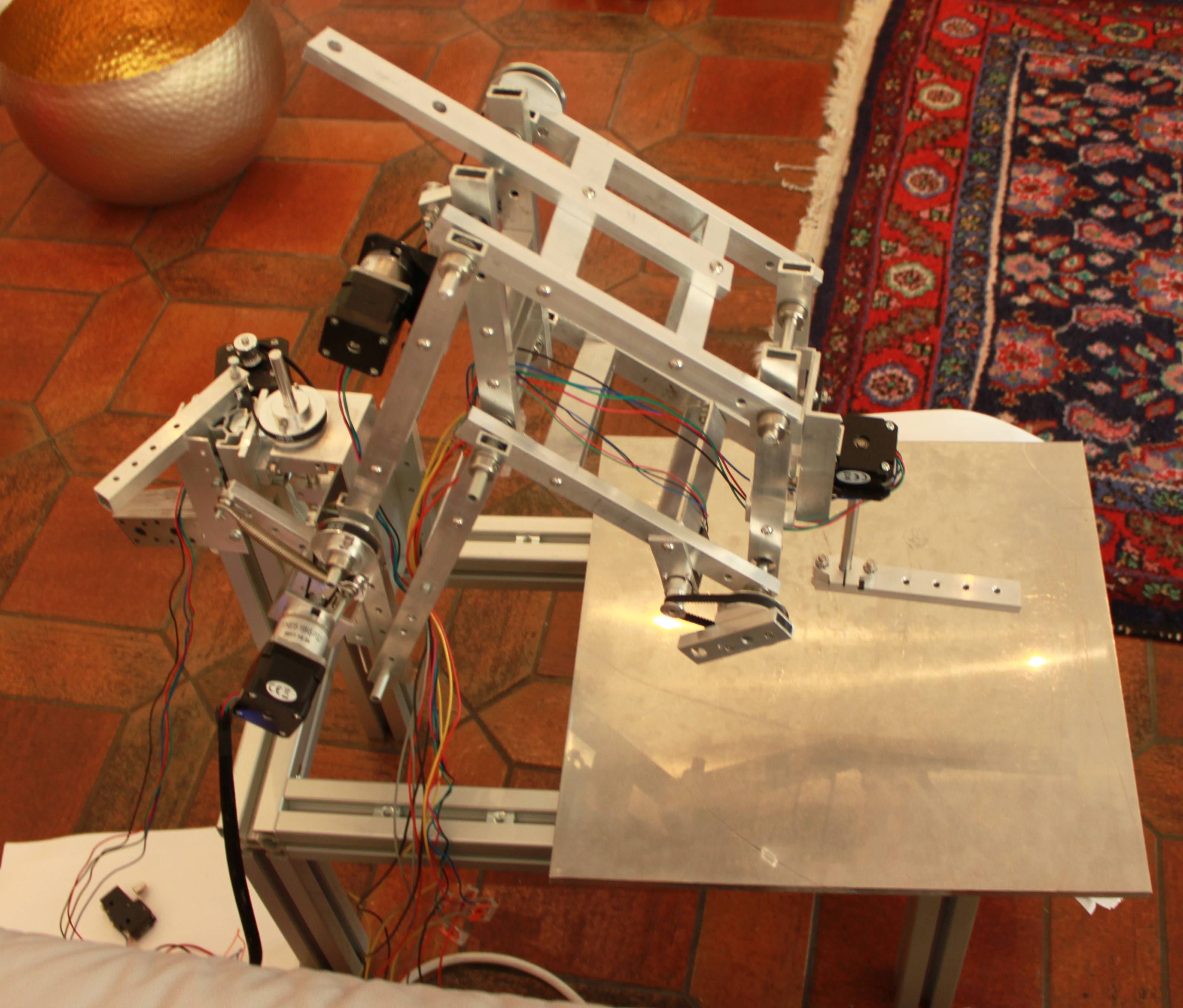
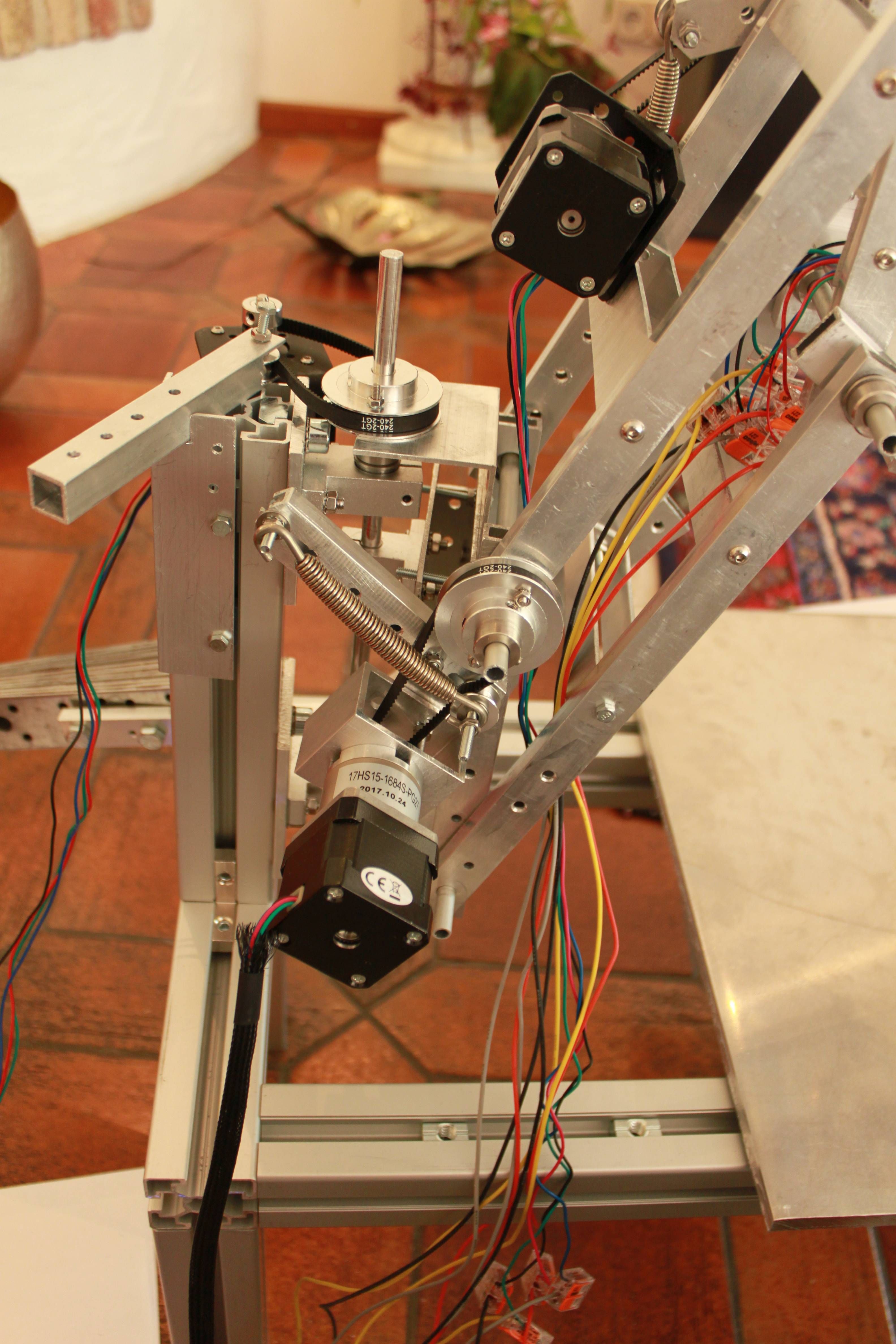
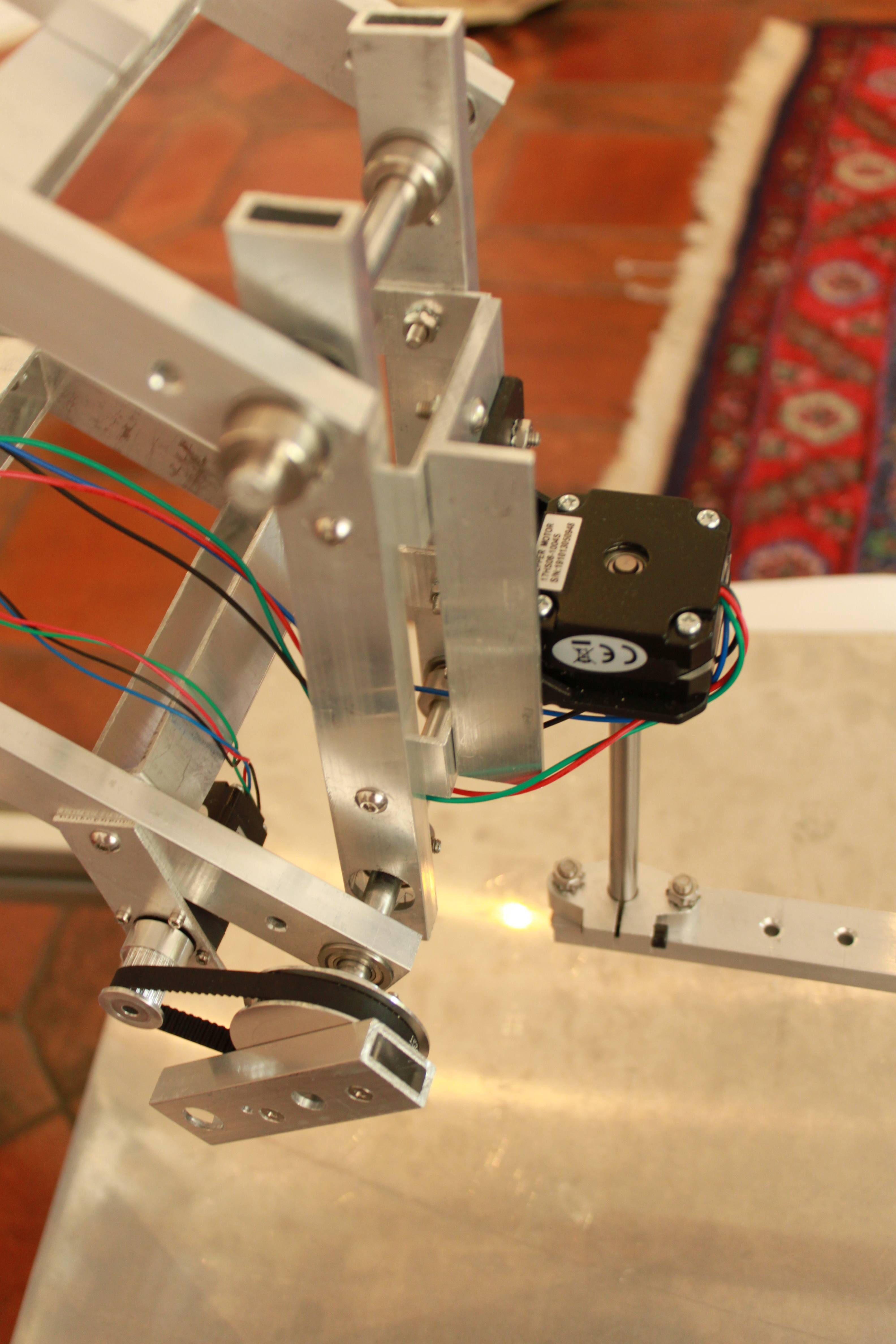
                                I have some images of my first pre-Prototype, before I will reconstruct it:

                                preprototype1.jpg

                                preprototype2.jpg

                                preprototype3.jpg

                                1 Reply Last reply Reply Quote 0
                                • undefined
                                  JoergS5
                                  last edited by JoergS5 10 Dec 2020, 10:09 12 Oct 2020, 09:06

                                  The first idea was to place Axis 1 behind the construction. This seemed to be a good idea because the axis is fixed at two points top and down and can be calibrated easily. But the disadvantages are, I have no good place to install actuator 2 and the counterweights have not much room also.

                                  Arm 2 and 3 are 27 cm and 20 cm long. For production the same length will be better, but I differed them to test firmware.

                                  The gears are insufficient. One stepper has a 1:27 gear, but the problem is the little 60 teeth pulley which is not sufficient. I'll produce 200 teeth pulleys as a next test now. The belt tensioning is very important also, because otherwise the belts slip very often.

                                  Arms 2 and 3 have 4 arm elements 20x10x2, connected horizontally by 100x20x2. The placement of the connectors are important, they define the possible axis angles.

                                  The upper and lower arm construction is 18 cm distance and makes sure the arm 4 is vertical at all times, so axis 5 is vertical also. I will remain this construction, but axis 5 supported at two hinges and with a gear.

                                  The actuator 4 on the third image is a dummy to check the firmware code for R0.

                                  I will try to avoid counterweights, because they support wavering of the construction.

                                  The hinges are constructed by 8 mm aluminium or steel shafts, F688 ball bearings with 16 mm holes and the 8 mm holes for the arms which are fixed to the shafts. Distances will be implemented by 8x12x0.5 washers.

                                  The arm connected pulleys are connected with screws to the arms, so they cannot slip when only connected to the shafts.

                                  One thing to be aware is, if turning off or installing new firmware, the steppers loose current and the robot arms fall down...

                                  The rebuild to the prototype will have axis 1 below the robot on a plate, bigger pulleys and a better belt tensioning system.

                                  undefined 1 Reply Last reply 13 Oct 2020, 18:45 Reply Quote 0
                                  • undefined
                                    tony73 @JoergS5
                                    last edited by 13 Oct 2020, 18:45

                                    @JoergS5

                                    Hello ! I'm sorry but yesterday I couldn't write to you, I saw the photos, to understand better, are you using this robot with some modifications, or do you have another one? however you have already worked so hard to do this!

                                    undefined 1 Reply Last reply 13 Oct 2020, 19:44 Reply Quote 0
                                    • undefined
                                      JoergS5 @tony73
                                      last edited by JoergS5 13 Oct 2020, 19:44

                                      @tony73 I constantly change this one. I am currently redesigning axis 1 and 2 and making the axis pulleys bigger. Then I will be able to install the extruder and print.

                                      The most work are the constant iterations, especially assembling and disassembling. I wished I have a robot who assembles it for me.... I could spare some effort with a good design program, but to understand some of the principles, I have to experiment.

                                      Currently important aspects to build the robot are:

                                      • hinges and arms without play and wobble
                                      • maximizing possible angles
                                      • find optimal gear ratio and avoid belt slippage
                                      • balancing the arms, avoiding counterweights by replacing the steppers (the steppers function as counterweights)
                                      • a procedure to protect against power off and arms falling down
                                      undefined 1 Reply Last reply 13 Oct 2020, 20:10 Reply Quote 0
                                      • undefined
                                        tony73 @JoergS5
                                        last edited by 13 Oct 2020, 20:10

                                        @JoergS5

                                        from the photos it seems to me that you have steppers with planetary gear motor 1:27 primary pulley how many teeth? secondary 60 teeth, the steppers are cut to what, full pitch, 1/2, 1/4, 1/8, 1/16, 1/32, etc .... the gearmotor how much size at birth? I would like to understand how much reduction is needed! since you would like to put 200 tooth pulleys instead of 60 tooth ones.

                                        undefined 1 Reply Last reply 13 Oct 2020, 21:51 Reply Quote 0
                                        • undefined
                                          JoergS5 @tony73
                                          last edited by 13 Oct 2020, 21:51

                                          @tony73 the gears were only for testing (and at axis 2 I had space problems), I want to avoid them because they have backlash. I will use a two or three step belt gear or a self constructed harmonic drive (axis 5). A 20/60 and 20:200 will result in 1:30.

                                          undefined 1 Reply Last reply 14 Oct 2020, 05:13 Reply Quote 0
                                          108 out of 389
                                          • First post
                                            108/389
                                            Last post
                                          Unless otherwise noted, all forum content is licensed under CC-BY-SA