Inconsistent results with optical encoder wheel filament sensor
-
@JohnOCFII and it passed those 100mm trough extruder and sensor and the wheel were rotating? that's rotating rather slow right, can you check the impulses with a multimeter maybe? analog one would work great?
-
@arhi said in Inconsistent results with optical encoder wheel filament sensor:
@JohnOCFII and it passed those 100mm trough extruder and sensor and the wheel were rotating? that's rotating rather slow right, can you check the impulses with a multimeter maybe? analog one would work great?
Yes. Also, the optical sensor board has an LED that was blinking at regular intervals.
Depending on the weather, I'm supposed to fly with a student tomorrow (weekend flight instructor). If not, I'll try this tomorrow.
Saleae LA should arrive Monday or Tuesday.
")
-
@JohnOCFII I'm more interested to see the levels you see on the duet board so measuring voltage between the signal pin (connlcd.encb) and gnd using voltmeter while slowly moving the encoder so to see what you have there for 0 (when that signal led is off) and what you have there for 1 (when that signal led is on) .. as I don't see a reason why would RRF detect these impulses for me and not for you unless there's something fishy with the voltage levels there ... how the cable is crymped etc etc..
-
So I've re-assembled the hot-end/extruder, and added some wiring extensions to connect to the Logic Analyzer. I was seeing incredibly strange outputs -- like this:
Pulse-type filament monitor on pin (connlcd.encb,connlcd.3), disabled, sensitivity 1.200mm/pulse, allowed movement 50% to 1500%, check every 5.0mm, measured sensitivity 0.000mm/pulse, measured minimum 0%, maximum 1052141% over 46.6mmSo I pulled the optical sensor off the case, and confirmed the encoder wheel is still moving as expected.
So while the print was running, I started using a flat print to interrupt the sensor on a sort of regular basis, and started to get "more normal" results again. And by normal -- I mean normal for my recent results...
Pulse-type filament monitor on pin (connlcd.encb,connlcd.3), disabled, sensitivity 1.200mm/pulse, allowed movement 30% to 1500%, check every 10.0mm, measured sensitivity 0.386mm/pulse, measured minimum 0%, maximum 6059% over 372.6mmI'm starting to wonder about wiring issues, or something else more related to the DUET. One thing you suggested was to try a different port, as this CONNLCD might be treated differently than the other ports.
(I've got more free time than expected today -- so will keep plugging at things today)
-
@JohnOCFII Hey John, I've been trying to keep up with this thread and I have a question you may have answered already:
How is the receiver part of your optical interruptor connected to your Duet?
Do you have a pull-up or pull-down resistor on the signal that goes to the Duet?If you got the digital-only Saleae you won't be able to see if there's a level problem due to a missing or too-large pull-resistor.
-
@alankilian said in Inconsistent results with optical encoder wheel filament sensor:
@JohnOCFII Hey John, I've been trying to keep up with this thread and I have a question you may have answered already:
How is the receiver part of your optical interruptor connected to your Duet?
Do you have a pull-up or pull-down resistor on the signal that goes to the Duet?If you got the digital-only Saleae you won't be able to see if there's a level problem due to a missing or too-large pull-resistor.
The optical sensor is connected to pins 1,2,3 on the CONN_LCD connector. I'd previously used this connection for a basic physical endstop-type filament sensor. I've tried the optical sensor with, and without the pull-up as indicated by including the "^" in the configuration string, but didn't see a noticeable change in behavior.
https://duet3d.dozuki.com/Wiki/RepRapFirmware_3_overview#Section_Pin_names_for_Duet_2_WiFi_Ethernet
I'm getting the Logic 8, which appears to have analog inputs. https://www.saleae.com
Also - right now I've hooked up a BitScope Micro, which I ordered a few years ago, but never used. When I hook it up to GND and the signal pin, I see a bit of noise, but no change when I interrupt the optical sensor beam. On the sensor itself breaking the beam turns off an LED. Perhaps no data flows to the Duet when a print isn't running?
I've never used a Logic Analyzer or O-Scope before, so this is all new to me.
-
Both the LED-side and the receive-side of the interrupter need to be hooked up "in the right way"
Can you post which connection on the Duet is connected to which connection on the optical interrupter?
Also, can you post the name/number of the interrupter or a data sheet?It's pretty easy to get one side or the other backwards. AND it's pretty easy to fix!
The new Logic 8 will be great.
I have the very very old digital only Logic 8 as well as an old Logic 16 Pro that does both analog and Digital, so I can certainly help you setup and look at the signal when you get that. -
@alankilian said in Inconsistent results with optical encoder wheel filament sensor:
Can you post which connection on the Duet is connected to which connection on the optical interrupter?
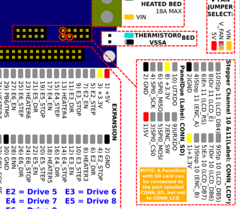
Duet Pin 1 (+3.3) <---> Pin labeled V on sensor
Duet Pin 2 (GND) <--> Pin labeled G on sensor
Duet Pin 3 (STOP 10 - ENC_B) <--> Pin labeled S on sensorAlso, can you post the name/number of the interrupter or a data sheet?
The markings on the unit are 70T2. These are sensors I bought: https://www.ebay.com/itm/4-Pieces-Optical-Endstop-Limit-Switch-RAMPS-1-4-Board-3D-Printer-3Pin-Cable-A27/254260205504
It's pretty easy to get one side or the other backwards. AND it's pretty easy to fix!
The new Logic 8 will be great.
I have the very very old digital only Logic 8 as well as an old Logic 16 Pro that does both analog and Digital, so I can certainly help you setup and look at the signal when you get that.Excellent -- and thank you!
-
Hmmmmm.
How do you know if that's supposed to have 5 Volts or 3.3 Volts?
And if it is supposed to pull the signal high or low?
And if you need to add an extra resistor or not?(I'll do some googling and see if I can answer my own questions.)
-
@alankilian said in Inconsistent results with optical encoder wheel filament sensor:
Hmmmmm.
How do you know if that's supposed to have 5 Volts or 3.3 Volts?
And if it is supposed to pull the signal high or low?
And if you need to add an extra resistor or not?(I'll do some googling and see if I can answer my own questions.)
I don't. Just going off the recommendations of the guy who designed this filament sensor project: https://www.thingiverse.com/thing:4445504Good thing I consider this just a learning experience. Because even at the end of the day, Best case it seems I'll be stuck with a 20-40mm "window" of filament passage before it'll trigger an issue. Might just go back to the switch for "filament out". It won't catch jams, but it'll reliably catch the case of filament out.
But first, I'd like to figure out why my results are so much worse than what @fractalengineer sees.
-
@arhi said in Inconsistent results with optical encoder wheel filament sensor:
@JohnOCFII I'm more interested to see the levels you see on the duet board so measuring voltage between the signal pin (connlcd.encb) and gnd using voltmeter while slowly moving the encoder so to see what you have there for 0 (when that signal led is off) and what you have there for 1 (when that signal led is on) .. as I don't see a reason why would RRF detect these impulses for me and not for you unless there's something fishy with the voltage levels there ... how the cable is crymped etc etc..
Voltage settles out at 3.2 when I pass a solid object between the optical sensor "arms." When nothing is between the arms, the voltage is not a clean, solid 0.0 but hovers in the 0.300-0.400 range.
And also remember, this optical sensor board has an LED that is lit when there is no object breaking the beam, which turns off when the beam is broken.
It seems like the sensor is sending what amounts to "on" or "off" but the Duet isn't dealing with it properly. This is firmware 3.1.1 on a Duet 2 Ethernet board.
-
@JohnOCFII dunno I don't understand why firmware is not reading those pulses if they are around 0.2V and 3.2V they should be read properly on the input pin. Maybe @dc42 can shed some light on what might be happening, and how to test/debug. I'm clueless at this point
-
@JohnOCFII Those are perfect values for this sensor and the Duet should have no problems detecting them as pulses.
I'll take a look deeper and we can see what the waveforms look like when you have the logic analyzer.
-
The Logic Analyzer arrived! Here's some data.

-
@JohnOCFII that looks ok, signals are more/less clean ... should work 1/1
if you grab a longer piece, do you see that during constant extrusion move signals are evenly spaced as one would expect?
levels seem ok, ~3V and ~0V, timing seem ok .. using the "extruder endstop" input is the only other idea I have.. don't see why would that make any difference but I use the encoder endstop input and it works for me
... now I still have some variance but I never reproduced this with many impulses and still "no data" on the sensor reading... @dc42 wrote that part of the code iirc and he should be able to say what might be wrong, the code for the pulse sensor itself, I looked month or two ago (and for laser sensor too) and I did not find anything weird there but.. -
That waveform looks OK.
Can you try commanding something like a 120mm extrusion slowly and then turn the wheel so that you have 100 notches pass and see if you get near the right amount of detected extrusion?
While capturing using the Saleae so we can also see the signal?
If you could then post the Saleae capture file anyone can download the Saleae software and take a look at it with you.
-
@alankilian said in Inconsistent results with optical encoder wheel filament sensor:
Can you try commanding something like a 120mm extrusion slowly and then turn the wheel so that you have 100 notches pass and see if you get near the right amount of detected extrusion?
With the unit assembled, I can't visually see the encoder wheel. I can certainly run 120mm and we can see what the Logic Analyzer sees.
If you could then post the Saleae capture file anyone can download the Saleae software and take a look at it with you.
So far, my Saleae experience is connecting lead 0 and ground to the ground and signal connection to the optical sensor. I hit the big green button to start capture.
I need to do a bit more reading to see if there is anything else I should be setting up for a good capture.
Progress might be slow until Sunday, but I'll do what I can to make progress.
I really appreciate your hanging with me on this, @arhi and @alankilian
John
-
@JohnOCFII You don't need to connect lead #0 to ground.
You can just connect one of the GND leads to ground and lead #0 to your signal and then you can turn off the other signals for capture.
You can capture as slowly as the analyzer will run to make your capture files small.
Make sure you're set to 3.3 Volts also.
Then green-arrow and extrude.
Stop and File->Save Capture and you can post it.SeemeCNC Rostock Max V3 converted to V3.2 with a Duet2 Ethernet Firmware 3.2 and SE300
-
@alankilian said in Inconsistent results with optical encoder wheel filament sensor:
You can just connect one of the GND leads to ground and lead #0 to your signal and then you can turn off the other signals for capture.
Yes that is what I did - I described it poorly.
You can capture as slowly as the analyzer will run to make your capture files small.
Make sure you're set to 3.3 Volts also.
Then green-arrow and extrude.
Stop and File->Save Capture and you can post it.Sounds good. I've been slammed with meetings the last couple of days. I'll see if I can set this up tonight.
-
@alankilian said in Inconsistent results with optical encoder wheel filament sensor:
Then green-arrow and extrude.
Stop and File->Save Capture and you can post it.I set up a capture during a vase mode cylinder print. Speed was 15mm/sec doing the vase. This was about the first 1/3rd of a 30 minute print. I know this isn't quite as controlled an example as a pure feed of 1000mm, but I needed to run the print anyway.
I captured this using the new Saleae Logic alpha software, version 2.3.13.
The capture is about 390 MB compressed (on disk). It's got both the digital and analog capture. I suppose I could have turned off the analog and saved some space.
Here's a link to the capture file: https://1drv.ms/u/s!ApuOkxTDmZEzgfznb3Mf2-ULLBN65XQ?e=cKZycH
And here's a timelapse: https://youtu.be/FcXaF9faE70
John