mirrored 3 d printed parts
-
Hello all,
I recently came across the following problem: my parts are printed in mirrored orientation
Bellow you have a photo of the printed part In the top view , the end switches ( home for x and y ) are positioned at the top left corner. Z is being homed using a bl touch .
Bellow you have the position of the part in the Slicer (Simplify3d), given the orientation of the axes on the machine :
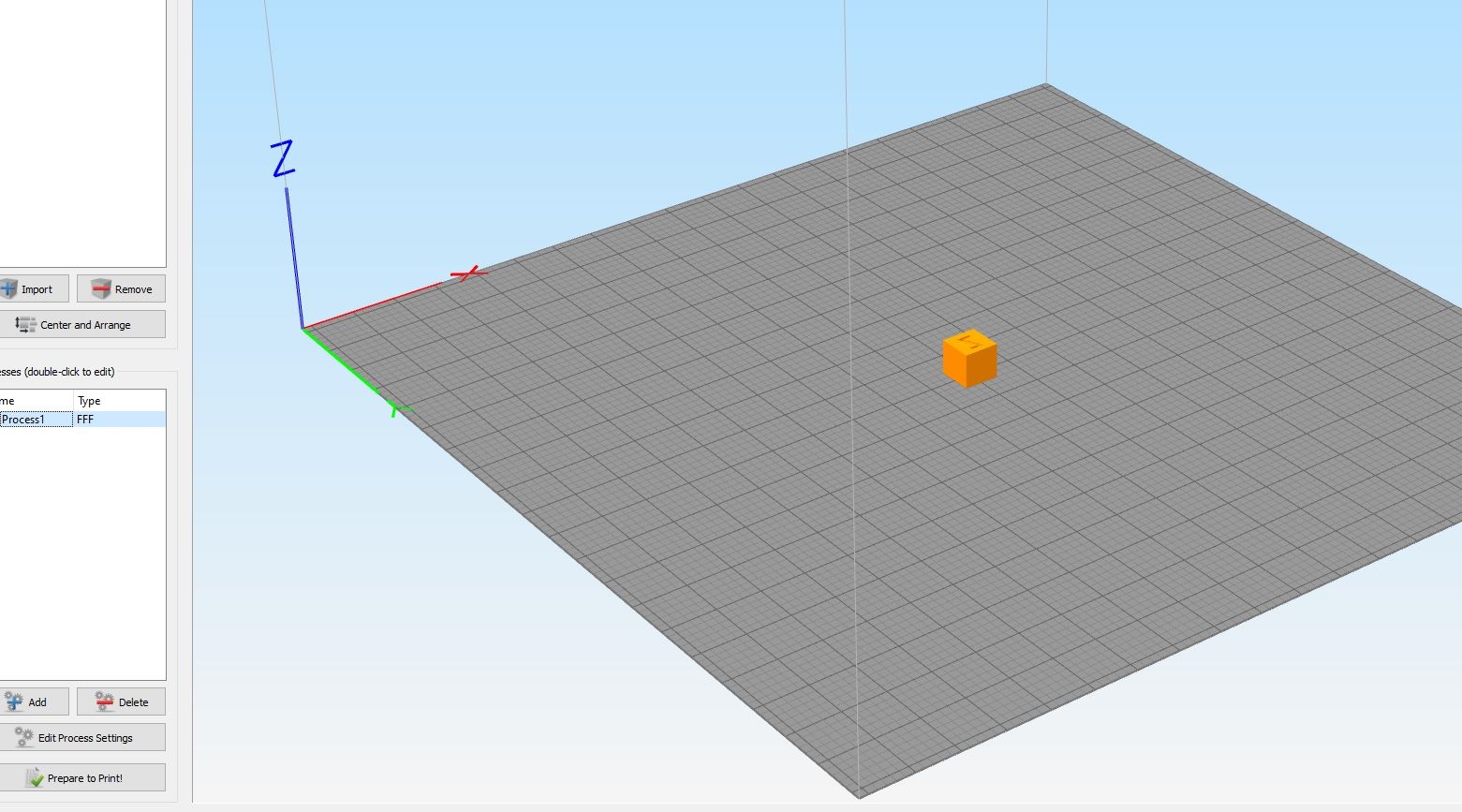
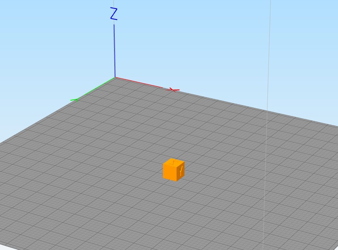
There are no axes flipped in the in the machine settings
I decided to flip the y axis , but still to no avail

-
What type of printer kinenatics? Share your config?
-
For cartsian and corexy, the homing is to the front left corner.
-
You can home wherever you like, could shift the origin as you like as well, but the direction of the axes has to comply with whatever coordinate system is in use.
Both the drawing and the slicer preview looks to have the y axis inverted compared to a normal cartesian printer, but if firmware, slicer and user are all aboard then it should still work, no? (Iirc Teartime does something similar with their stuff, but prints come out right way around)
-
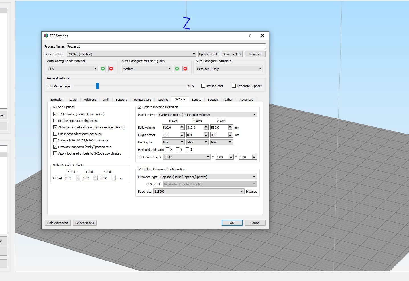
The axis reference in the image from the slicer shows a left hand rule coordinate system. They usually default to right hand rule to match CAD software. Your printer should be set up for right hand rule coordinates, again, to match CAD software.
If the slicer is thinking in terms of left hand rule, prints are going to be mirrored.
-
Hello @bearer, it's a core XY 3d printer . Here's the config :
; Configuration file for Duet WiFi (firmware version 3)
; executed by the firmware on start-up
;
; generated by RepRapFirmware Configuration Tool v3.1.4 on Mon Oct 05 2020 11:50:08 GMT+0300 (Eastern European Summer Time); General preferences
G90 ; send absolute coordinates...
M83 ; ...but relative extruder moves
M550 P"Oscar" ; set printer name
M669 K1 ; select CoreXY mode; Network
M551 P"" ; set password
M552 S1 ; enable network
M586 P0 S1 ; enable HTTP
M586 P1 S1 ; enable FTP
M586 P2 S0 ; disable Telnet; Drives
M584 X1 Y0 Z2 E3:4 ; set drive mapping; INIT:X=0; Y=1; Z2;E3:4
M569 P0 S0 ; physical drive 0 goes backwards
M569 P1 S0 ; physical drive 1 goes backwards
M569 P2 S1 ; physical drive 2 goes FORWARDS
M569 P3 S1 ; physical drive 3 goes FORWARDS
M569 P4 S0 ; physical drive 4 goes backwardsM350 X16 Y16 Z16:16 E16:16 I1 ; configure microstepping with interpolation ; INIT- M350 X16 Y16 Z16 E16:16 I1
M92 X160.00 Y160.00 Z3200.00 E843.26:830.8 ; set steps per mm
M566 X600.00 Y600.00 Z12.00 E120.00:120.00 ; set maximum instantaneous speed changes (mm/min)set x and y to 600 from 900
M203 X6000.00 Y6000.00 Z360.00 E1200.00:1200.00 ; set maximum speeds (mm/min)
M201 X250.00 Y250.00 Z20.00 E250.00:250.00 ; set accelerations (mm/s^2)x and y 250 from 500
M906 X1100 Y1100 Z1200 E1200:1200 I80 ; set motor currents (mA) and motor idle factor in per cent changed X1200 Y1200 to X1100 Y1100
M84 S30 ; Set idle timeout
; Pressure advance
M572 D0:1 S0.05:0.05 ; enabled Pressure advance for both extruders
;M572 D0:1 S0.035:0.035; Axis Limits
M208 X0 Y0 Z0 S1 ; set axis minima
M208 X600 Y600 Z525 S0 ; set axis maxima; Endstops
M574 X1 S1 P"!xstop" ; configure active-high endstop for low end on X via pin xstop -added "! to xstop"
M574 Y1 S1 P"!ystop" ; configure active-high endstop for low end on Y via pin ystop - added"! to xstop"
M574 Z1 S2 ; configure Z-probe endstop for low end on Z; Z-Probe
M950 S0 C"duex.pwm5" ; create servo pin 0 for BLTouch
M558 P9 C"^zprobe.in" H5 F120 T6000 ; set Z probe type to bltouch and the dive height + speeds
G31 P25 X20 Y37 Z2.49 ; set Z probe trigger value, offset and trigger height- changed from 3.5 to 2.19 to -0.797,to 2.4 to 2.49
M557 X40:520 Y80:520 P20 ; define mesh grid changed S20 to P3 to P20; Heaters
M308 S0 P"bedtemp" Y"thermistor" T100000 B4138 ; configure sensor 0 as thermistor on pin bedtemp
M950 H0 C"bedheat" T0 ; create bed heater output on bedheat and map it to sensor 0
M307 H0 B0 S1.00 ; disable bang-bang mode for the bed heater and set PWM limit
M140 H0 ; map heated bed to heater 0
M143 H0 S130 ; set temperature limit for heater 0 to 130C
M308 S1 P"e0temp" Y"thermistor" T100000 B4725 C7.06e-8 ; configure sensor 1 as thermistor on pin e0temp
M950 H1 C"e0heat" T1 ; create nozzle heater output on e0heat and map it to sensor 1
M307 H1 B0 S1.00 ; disable bang-bang mode for heater and set PWM limit
M308 S2 P"e1temp" Y"thermistor" T100000 B4725 C7.06e-8 ; configure sensor 2 as thermistor on pin e1temp
M950 H2 C"e1heat" T2 ; create nozzle heater output on e1heat and map it to sensor 2
M307 H2 B0 S1.00 ; disable bang-bang mode for heater and set PWM limit; Fans
M950 F0 C"fan0" Q500 ; create fan 0 on pin fan0 and set its frequency
M106 P0 S1 H-1 ; set fan 0 value. Thermostatic control is turned off
M950 F1 C"fan1" Q500 ; create fan 1 on pin fan1 and set its frequency
M106 P1 S1 H-1 ; set fan 1 value. Thermostatic control is turned off; Tools
M563 P0 S"Tool 1" D0 H1 F0 ; define tool 0
G10 P0 X0 Y0 Z0 ; set tool 0 axis offsets
G10 P0 R0 S0 ; set initial tool 0 active and standby temperatures to 0C
M563 P1 S"Tool 2" D1 H2 F1 ; define tool 1
G10 P1 X0 Y0 Z0 ; set tool 1 axis offsets
G10 P1 R0 S0 ; set initial tool 1 active and standby temperatures to 0C; Custom settings are not defined
M912 P0 S-16.95 ; adjustment of the MCU temp read; Miscellaneous
M575 P1 S1 B57600 ; enable support for PanelDue
M911 S10 R11 P"M913 X0 Y0 G91 M83 G1 Z3 E-5 F1000" ; set voltage thresholds and actions to run on power loss
M501 ; load saved parameters from non-volatile memory -
So do you want the config to match the slicer, or the slicer to match the config? Looks like config is right hand, and slicer is left hand.
Unless you have a particularly good reason to have the slicer left handed I'd change the slicer settings to be a right hand coordinate system.
https://en.wikipedia.org/wiki/Cartesian_coordinate_system#Orientation_and_handedness
-
It looks like you found the consequence of a left handed coordinate system.
https://forum.duet3d.com/topic/19049/trouble-with-homing-the-x-and-y-axes-on-a-core-xy-printer/26
Did my post from your previous thread make more sense now?
If you have the firmware setup correctly, it's a matter now of getting your slicer back to normal. You probably had it flipped to correct for the firmware being backwards before.
-
I found that S3D uses a left hand coordinate system unless I check "Flip Y axis".
-
Hi,
Just FYI the position of the end stop sensors do not have to be treated as if they correspond to X=0 Y=0.
Homing doesn't mean moving to 0,0 - it simply means moving to some known position so the firmware has a reference for where the moving bits are.
On one of my printers homing is to X min and Y max. On the other homing is to X max and Y max.
Yet on both machines 0,0 is at the left front.
Frederick
-
Hello all,
Thank you all for the insight regarding this issue.It appears that I've set the y axis in clockwise direction. Is there a way to set the homing on +y axis, instead of homing to y=0?
-
Do i have to set the min and max axis values via the G92 command?
-
Thank you all for the insight regarding this issue.It appears that I've set the y axis in clockwise direction. Is there a way to set the homing on +y axis, instead of homing to y=0?
yes, change the end stop definition for y. use Y2 instead of Y1.
https://duet3d.dozuki.com/Wiki/Gcode#Section_M574_Set_endstop_configurationDo i have to set the min and max axis values via the G92 command?
i think you want m208
https://duet3d.dozuki.com/Wiki/Gcode#Section_M208_Set_axis_max_travel -
Based on the images you posted, your mirrored prints are due to the slicer being set for a left hand rule coordinate system. That needs a fix in the slicer, not the printer config.
-
I kinda assumed the slicer was corrected and the firmware was also in need of a change. But good call; should clarify what the goal is here.
-
As pointed out before
Usually for a cartesian if you stand before it on the side that is the handling/front-side (where most printers have their screen) the left corner that is closest to you is the machine-csys (G53) with your print-plate beeing only in the positive space, that means to the right is the x-axis, back goes the y-axis and up goes the z-axis (you might have to invert an axis in the config.g if you have a moving plate and not a moving tool on the axis)
(The csys looks like in the old math classes") ) You can check with your printer after levelling the plate what it shows in DWC as "Height map", an example for a cartesian here:
) You can check with your printer after levelling the plate what it shows in DWC as "Height map", an example for a cartesian here: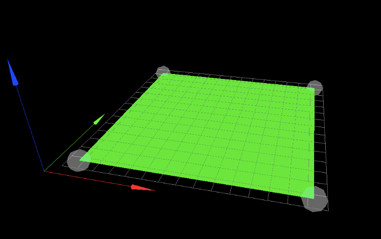
with the same rgb for xyz
As pointed out before looking at the pictures you posted, you have to adjust the axis in your slicer! And since your parts were mirrored no need to touch the printer config.g then - should work with an adjusted slicer...
but so many good suggestions have been made you might just ignore this post
Happy printing!
-
Hello @mrehorstdmd ,
In the firmware I've set the homing position to max y, so I could set the slicer for the right hand coord system. I also tested the movement on the x and y axes and had to change the quadrant in which x and y move in the positive direction.
-
@campeancalin Homing position is set by the endstops. They can be anywhere. The origin is selected by the values you assign to the homing position at the endstops.
Looking at the image immediately above, the origin (X=0, Y=0) is set to the front left corner. The arrows point in the + direction for each axis. If you put put the Y axis endstop at the front edge it would be at Y=0, or at the back edge it would be at Y=Ymax. Likewise you could put the X endstop along the left edge and it would be at X=0, or you could put it at the right edge and it would be at Xmax.
So choose the location of the origin, place the switches wherever is convenient, and assign the correct ordinate values when the endstops are triggered and everything will be fine.
The origin doesn't have to be at a corner of the bed. I find it very convenient to put it at the center of the bed. That makes it easy to switch between different slicers (and sometimes different printers) with minimal messing around to ensure that prints get placed on the center of the bed. Using the image above, if the bed is 300 x 300 and endstops are at the right and rear edges (Xmax and Y max), when the X endstop is triggered you set the value to X=150, and when the Y endstop is triggered, you set the value to Y=150. The printer will understand that the left edge is at X=-150, and the front edge is at Y=-150.
Some people assign the origin to the right rear corner of the bed which is a 180 degree rotation of the coordinate indicator in the image above- i.e. Xmax is to the left and Ymax is at the front of the bed. That's OK, it's still right hand rule, but the slicers usually assume that the coordinates are as shown in the image above. That means if your printer's origin is set up to the right rear corner of the bed, the slicer will show you the view from the rear of the printer. If you want the slicer to show the view from the front, just as you were looking at the printer, then Xmax should be to the right and Y max should be to the rear.
-
I had the same problem.
--> worong wiring ?
I switched y and x axis motor cable on the duet board.
Problem solved.
May check this