mirrored 3 d printed parts
-
So do you want the config to match the slicer, or the slicer to match the config? Looks like config is right hand, and slicer is left hand.
Unless you have a particularly good reason to have the slicer left handed I'd change the slicer settings to be a right hand coordinate system.
https://en.wikipedia.org/wiki/Cartesian_coordinate_system#Orientation_and_handedness
-
It looks like you found the consequence of a left handed coordinate system.
https://forum.duet3d.com/topic/19049/trouble-with-homing-the-x-and-y-axes-on-a-core-xy-printer/26
Did my post from your previous thread make more sense now?
If you have the firmware setup correctly, it's a matter now of getting your slicer back to normal. You probably had it flipped to correct for the firmware being backwards before.
-
I found that S3D uses a left hand coordinate system unless I check "Flip Y axis".
-
Hi,
Just FYI the position of the end stop sensors do not have to be treated as if they correspond to X=0 Y=0.
Homing doesn't mean moving to 0,0 - it simply means moving to some known position so the firmware has a reference for where the moving bits are.
On one of my printers homing is to X min and Y max. On the other homing is to X max and Y max.
Yet on both machines 0,0 is at the left front.
Frederick
-
Hello all,
Thank you all for the insight regarding this issue.It appears that I've set the y axis in clockwise direction. Is there a way to set the homing on +y axis, instead of homing to y=0?
-
Do i have to set the min and max axis values via the G92 command?
-
Thank you all for the insight regarding this issue.It appears that I've set the y axis in clockwise direction. Is there a way to set the homing on +y axis, instead of homing to y=0?
yes, change the end stop definition for y. use Y2 instead of Y1.
https://duet3d.dozuki.com/Wiki/Gcode#Section_M574_Set_endstop_configurationDo i have to set the min and max axis values via the G92 command?
i think you want m208
https://duet3d.dozuki.com/Wiki/Gcode#Section_M208_Set_axis_max_travel -
Based on the images you posted, your mirrored prints are due to the slicer being set for a left hand rule coordinate system. That needs a fix in the slicer, not the printer config.
-
I kinda assumed the slicer was corrected and the firmware was also in need of a change. But good call; should clarify what the goal is here.
-
As pointed out before
Usually for a cartesian if you stand before it on the side that is the handling/front-side (where most printers have their screen) the left corner that is closest to you is the machine-csys (G53) with your print-plate beeing only in the positive space, that means to the right is the x-axis, back goes the y-axis and up goes the z-axis (you might have to invert an axis in the config.g if you have a moving plate and not a moving tool on the axis)
(The csys looks like in the old math classes") ) You can check with your printer after levelling the plate what it shows in DWC as "Height map", an example for a cartesian here:
) You can check with your printer after levelling the plate what it shows in DWC as "Height map", an example for a cartesian here: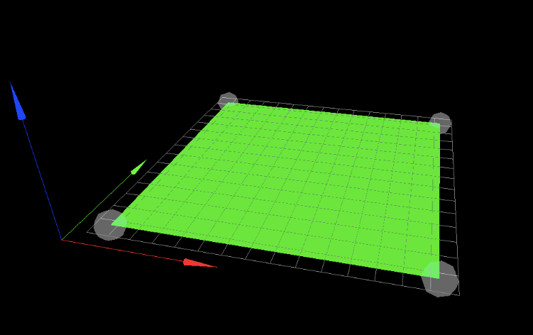
with the same rgb for xyz
As pointed out before looking at the pictures you posted, you have to adjust the axis in your slicer! And since your parts were mirrored no need to touch the printer config.g then - should work with an adjusted slicer...
but so many good suggestions have been made you might just ignore this post
Happy printing!
-
Hello @mrehorstdmd ,
In the firmware I've set the homing position to max y, so I could set the slicer for the right hand coord system. I also tested the movement on the x and y axes and had to change the quadrant in which x and y move in the positive direction.
-
@campeancalin Homing position is set by the endstops. They can be anywhere. The origin is selected by the values you assign to the homing position at the endstops.
Looking at the image immediately above, the origin (X=0, Y=0) is set to the front left corner. The arrows point in the + direction for each axis. If you put put the Y axis endstop at the front edge it would be at Y=0, or at the back edge it would be at Y=Ymax. Likewise you could put the X endstop along the left edge and it would be at X=0, or you could put it at the right edge and it would be at Xmax.
So choose the location of the origin, place the switches wherever is convenient, and assign the correct ordinate values when the endstops are triggered and everything will be fine.
The origin doesn't have to be at a corner of the bed. I find it very convenient to put it at the center of the bed. That makes it easy to switch between different slicers (and sometimes different printers) with minimal messing around to ensure that prints get placed on the center of the bed. Using the image above, if the bed is 300 x 300 and endstops are at the right and rear edges (Xmax and Y max), when the X endstop is triggered you set the value to X=150, and when the Y endstop is triggered, you set the value to Y=150. The printer will understand that the left edge is at X=-150, and the front edge is at Y=-150.
Some people assign the origin to the right rear corner of the bed which is a 180 degree rotation of the coordinate indicator in the image above- i.e. Xmax is to the left and Ymax is at the front of the bed. That's OK, it's still right hand rule, but the slicers usually assume that the coordinates are as shown in the image above. That means if your printer's origin is set up to the right rear corner of the bed, the slicer will show you the view from the rear of the printer. If you want the slicer to show the view from the front, just as you were looking at the printer, then Xmax should be to the right and Y max should be to the rear.
-
I had the same problem.
--> worong wiring ?
I switched y and x axis motor cable on the duet board.
Problem solved.
May check this