Duet3D Logo Duet3D
    • Tags
    • Documentation
    • Order
    • Register
    • Login

    First Layer and Extrusion Problems

    Scheduled Pinned Locked Moved
    Tuning and tweaking
    6
    121
    5.9k
    Loading More Posts
    • Oldest to Newest
    • Newest to Oldest
    • Most Votes
    Reply
    • Reply as topic
    Log in to reply
    This topic has been deleted. Only users with topic management privileges can see it.
    • Vetiundefined
      Veti @Frederik
      last edited by

      @Frederik
      no the standard is 0,0 is bottom left.

      1 Reply Last reply Reply Quote 0
      • Frederikundefined
        Frederik @Veti
        last edited by

        @Veti ok , one moment i will check it with my multimeter... could it be a bad crimp ?

        1 Reply Last reply Reply Quote 0
        • fcwiltundefined
          fcwilt @Frederik
          last edited by

          @Frederik said in First Layer and Extrusion Problems:

          I could only mount the Endstop on the left side of my carriage and the Y Endstop is at the back

          Hi,

          The location of the end stop sensors do not determine where 0, 0 is located.

          End stop sensors are used during homing, true, but they only "tell" the firmware the hardware is in a known location, which may be at the axis min, the axis max or somewhere else.

          It is common to have 0, 0 at the left front corner of the bed. Another option is to have 0, 0 at the center of the bed - that is the what I do.

          Frederick

          Printers: a E3D MS/TC setup and a RatRig Hybrid. Using Duet 3 hardware running 3.4.6

          Frederikundefined 1 Reply Last reply Reply Quote 0
          • Frederikundefined
            Frederik @fcwilt
            last edited by

            @fcwilt Ah ok, now i got it 🙂

            1 Reply Last reply Reply Quote 0
            • Frederikundefined
              Frederik
              last edited by

              so, now to a new start... nozzle free again, probe working (was a light loose crimp pin on the black wire)

              1 Reply Last reply Reply Quote 1
              • Frederikundefined
                Frederik
                last edited by

                ok ,looks good so far. i startet my first 20mm xyz test cube 🙂 fingers crossed , i hope it will run through without clogging

                1 Reply Last reply Reply Quote 1
                • Frederikundefined
                  Frederik
                  last edited by

                  This is my very first successful Print:

                  IMG_20201121_115328.jpg
                  IMG_20201121_115242.jpg
                  IMG_20201121_115220.jpg
                  IMG_20201121_115254.jpg

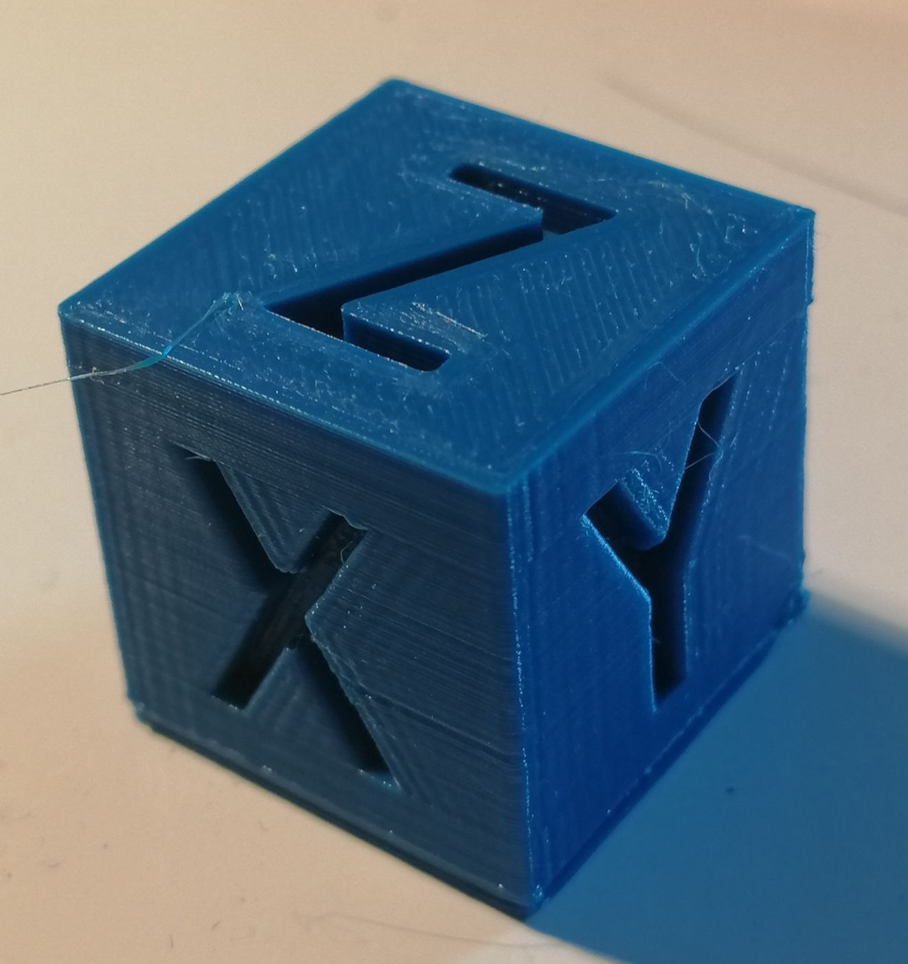
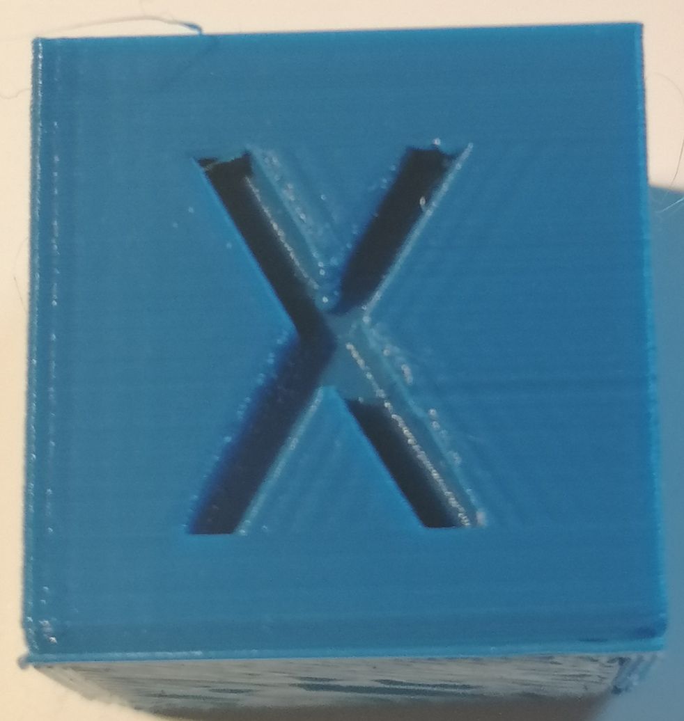
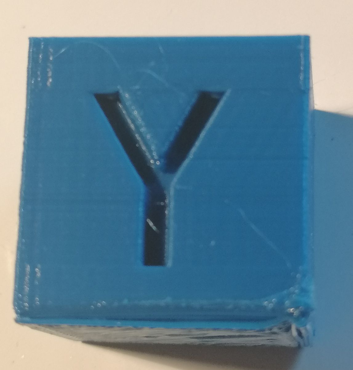
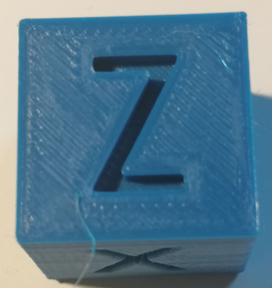
                  It should be 20x20x20
                  And the actual dimensions are

                  X 20.10 MM WITH STEPS 160
                  Y 20.10 MM EITH STEPS 160
                  Z 20.40 MM WITH STEPS 400

                  1 Reply Last reply Reply Quote 1
                  • Vetiundefined
                    Veti
                    last edited by

                    you have not calibrated you e steps yet

                    Frederikundefined 1 Reply Last reply Reply Quote 0
                    • Frederikundefined
                      Frederik @Veti
                      last edited by

                      @Veti i forgot E 830

                      Vetiundefined 1 Reply Last reply Reply Quote 0
                      • Vetiundefined
                        Veti @Frederik
                        last edited by

                        @Frederik said in First Layer and Extrusion Problems:

                        i forgot E 830

                        i dont know what you mean by that

                        here is a guide on how to calibration it
                        https://duet3d.dozuki.com/Guide/Ender+3+Pro+and+Duet+Maestro+Guide+Part+4:+Calibration/40#s165

                        Frederikundefined 1 Reply Last reply Reply Quote 0
                        • Frederikundefined
                          Frederik @Veti
                          last edited by

                          @Veti My extruder steps are correct. 100mm are 100mm

                          1 Reply Last reply Reply Quote 0
                          • Vetiundefined
                            Veti
                            last edited by

                            the bottom looks a bit strange, did you enable raft?

                            Frederikundefined 1 Reply Last reply Reply Quote 0
                            • Frederikundefined
                              Frederik @Veti
                              last edited by Frederik

                              @Veti brim was activated. but i´m struggling with the z offset a little bit. sometimes its really good , on the next try its scrubbing over the bed.
                              The cube was also printed on the backside of my buildplate. not the pei side to avoid any additional damage to my surface. 😞

                              i adjusted the bed to the subframe assembly with my digital calipers to ~ 0.05mm equal distances.

                              then i checked my bltouch mountig if it is perpenticular to the bed. that is also good.

                              then i homed z.

                              after that a true bed level with G32
                              another G32

                              Then mesh compensation with G29 and another G32 to Load the new Heightmap.

                              Now im testing with ABS Filament. because the pla before was constantly clogging in the heatbreak.

                              i adjustet my retraction to 1mm with 25mm/s speed and will see if it will be better. i have zero stringing with these settings.

                              Vetiundefined 1 Reply Last reply Reply Quote 0
                              • Vetiundefined
                                Veti @Frederik
                                last edited by

                                @Frederik said in First Layer and Extrusion Problems:

                                after that a true bed level with G32
                                another G32
                                Then mesh compensation with G29 and another G32 to Load the new Heightmap.

                                that is not a good idea. the G32 after the G29 will mess up the mesh. also after running G32 you need to establish a new Z

                                Frederikundefined A Former User? 2 Replies Last reply Reply Quote 0
                                • Frederikundefined
                                  Frederik @Veti
                                  last edited by Frederik

                                  @Veti oh, I didn't know that. Then I won´t do a G32 after the G28 anymore 🙂

                                  is the software handling everything after the G32 automatically from the heightmap every time I start a new print?

                                  A Former User? 1 Reply Last reply Reply Quote 0
                                  • A Former User?
                                    A Former User @Veti
                                    last edited by

                                    @Veti said in First Layer and Extrusion Problems:

                                    that is not a good idea. the G32 after the G29 will mess up the mesh. also after running G32 you need to establish a new Z

                                    If you have a bed.g like below you already re-establish the Z datum all in one go.......

                                    ; bed.g
                                    ;
                                    ; called to perform automatic bed compensation via G32
                                    ;
                                    G28                         ; Home all
                                    G30 P0 X2 Y-2 Z-99999       ; Probe near the front left lead-screw
                                    G30 P1 X152 Y278 Z-99999    ; Probe near the rear lead screw 
                                    G30 P2 X290 Y-2 Z-99999 S3  ; Probe near the front right lead-screw
                                    G30 P0 X2 Y-2 Z-99999       ; Probe near the front left lead-screw (Second Pass)
                                    G30 P1 X152 Y278 Z-99999    ; Probe near the rear lead screw (Second Pass)
                                    G30 P2 X290 Y-2 Z-99999 S3  ; Probe near the front right lead-screw (Second Pass) 
                                    G91                         ; Switch to relative positioning moves
                                    G1 H2 Z5 F8000              ; Drop the Z axis (the bed) by 5mm relative to its current position
                                    G90                         ; Revert back to absolute positioning moves
                                    G1 X160 Y155 F8000          ; Position the nozzle at the centre of the bed
                                    G30                         ; Probe and set the height as probed
                                    G29 S1 P"heightmap.csv"     ; Load the height map
                                    
                                    Frederikundefined 1 Reply Last reply Reply Quote 0
                                    • A Former User?
                                      A Former User @Frederik
                                      last edited by A Former User

                                      @Frederik said in First Layer and Extrusion Problems:

                                      @Veti oh, I didn't know that. Then I won´t do a G32 after the G28 anymore 🙂

                                      G32 must be initiated AFTER the printer has homed all axises otherwise the printer has NO reference to work from.

                                      Here is what the Duet G-Code dozuki lists G28 & G32 as :

                                      G28 Home

                                      Example

                                      G28 ; Home all axes

                                      The purpose of homing is to allow the printer to obtain a reference of where it is in space.

                                      G32: Run bed.g macro
                                      Parameters

                                      None

                                      Example

                                      G32:

                                      The firmware executes macro file bed.g. This macro normally uses G30 commands to probe the bed and then perform auto calibration of a delta printer (see Calibrating a delta printer), or perform bed leveling by moving the Z leadscrews independently, or display the manual corrections needed to the bed levelling screws.

                                      So if you do not carry out G28 before you attempt to carry out G32 you will receive and error message ; Not enough axises homed

                                      Unless the printer was already homed which is what G28 does anyway.....

                                      1 Reply Last reply Reply Quote 0
                                      • Frederikundefined
                                        Frederik @A Former User
                                        last edited by

                                        @CaLviNx Thank you, then i think is everything ready. i startet to print a fanchroud out of ABS. im very curious how it comes out.

                                        what would i have to change in my config.g to use a capazitive sensor with 3 wires ?

                                        is the connection on the duet 3 like: +5V, GND, and io.in ?

                                        what musst be changed in these lines ?

                                        ; Z-Probe
                                        M950 S0 C"io7.out"                                    ; create servo pin 0 for BLTouch
                                        M558 P9 C"^io7.in" H5 F120 T6000                      ; set Z probe type to bltouch and the dive height + speeds
                                        G31 P500 X0 Y0 Z1.8                                 ; set Z probe trigger value, offset and trigger height
                                        

                                        the last point , i want to change my mechanical endstop switches to optical ones.
                                        But what i am doing, the endstopps are lighting up but i cant get them to trigger.

                                        i´ve got 2 different ones.

                                        one with high level when no trigger
                                        and one with low level when no trigger

                                        2020-11-21_14h15_42.png

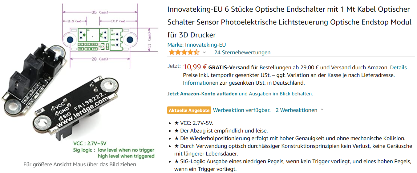
                                        but i cant get the mo work

                                        A Former User? Vetiundefined 2 Replies Last reply Reply Quote 0
                                        • A Former User?
                                          A Former User @Frederik
                                          last edited by A Former User

                                          @Frederik561

                                          Im sorry i only used that type of Z sensor when i first started with the duet years ago, I found them to be very unreliable, they were very susceptible to temp changes , so I have forgotten how I wired them up. I only use the Duet IR sensor now

                                          It would appear they would be as you say VCC, GND, SIG which would correspond with what you wrote.

                                          there is a section in the Dozuki on Z-Probes

                                          As for the optical end stops again I dont use them, I only use Omron mechanical switches, they operate fine even at high temps in a chamber.

                                          You might try inverting the signal on either of those two switches to see if that gets them working, or another thing is to check to see what triggers them, i dont know they might be looking for a metal or a dark colour to trigger them if they are an optical IR sensor

                                          Frederikundefined 1 Reply Last reply Reply Quote 0
                                          • Frederikundefined
                                            Frederik @A Former User
                                            last edited by

                                            @CaLviNx how do you like the mini ir sensor ? is it working better than the bltouch ?

                                            A Former User? 1 Reply Last reply Reply Quote 0
                                            • First post
                                              Last post
                                            Unless otherwise noted, all forum content is licensed under CC-BY-SA