Inconsistent results with optical encoder wheel filament sensor
-
@alankilian said in Inconsistent results with optical encoder wheel filament sensor:
@JohnOCFII I sent you a chat message with a contact at Duet3d who might be able to help you with a magnetic filament monitor parts kit.
Let me know if you didn't get the message and how to send it to you.
Weird -- I get emails for message updates, but not "chat" updates -- so I hadn't seen that message.
-
@alankilian said in Inconsistent results with optical encoder wheel filament sensor:
https://www.digikey.com/en/products/detail/texas-instruments/CD40106BE/376602
If you want help wiring it up, let me know.
I took the whole week off for Thanksgiving. Time to get back into this.
It looks like I connect pin 7 to ground, and pin 14 to 3.3V power.
It looks like most of the rest of the pins are paired. I'm not sure if it matters which pairs I use. Looks like I could connect from the optical sensor to Pin 1 (for input) and connect from Pin 2 (for output) to the Duet.
Would that be correct?
(This from the diagram on page 3) in the PDF below: https://www.ti.com/lit/ds/symlink/cd40106b.pdf?HQS=TI-null-null-digikeymode-df-pf-null-wwe&ts=1606236503315

-
@JohnOCFII That's all correct.
It doesn't matter which inverter you use. You just need to make sure to use the input of one inverter and the output of the same inverter of course.
")
I don't remember what your optical receiver circuit looks like, so you might need either a pull-up or a pull-down on the input to the Schmitt trigger inverter pin #1.
You can connect pin #2 directly to the Duet input pin.
-
@alankilian said in Inconsistent results with optical encoder wheel filament sensor:
I don't remember what your optical receiver circuit looks like, so you might need either a pull-up or a pull-down on the input to the Schmitt trigger inverter pin #1.
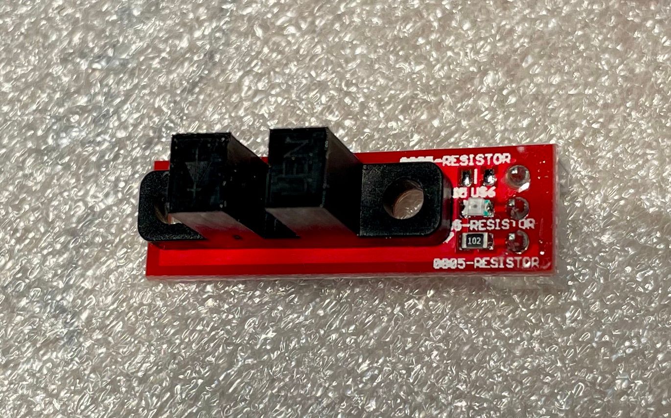
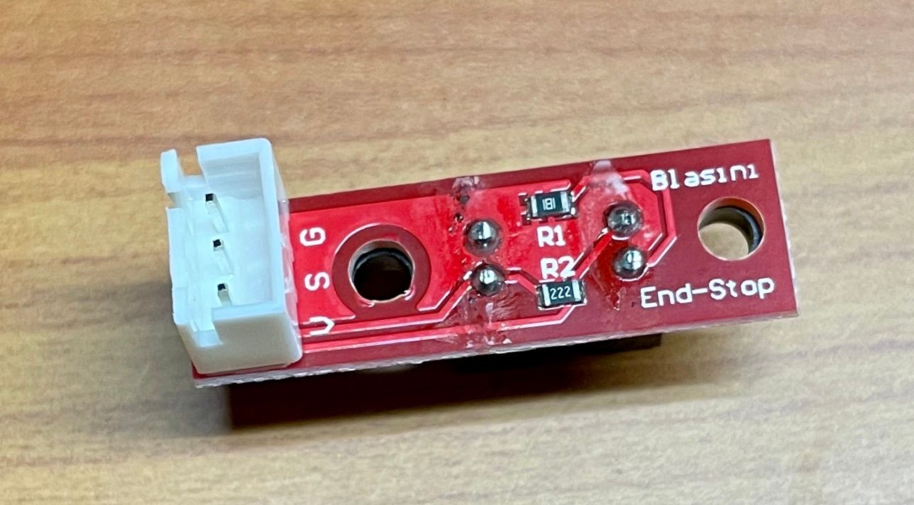
Here are two photos of the optical sensor. Not sure it is clear enough to indicate presence or absence of the pull-up or pull-down resistors.
-
@JohnOCFII
R1 is a 180 Ohm resistor in series with the emitter LED.
R2 is a 2,200 Ohm resistor to pull UP the receiver signal line.The resistor on the top is a 1,000 Ohm resistor in series with the LED on top. Is that a power-on LED?
So I would just hook it directly to the input of the Schmitt-inverter. No pull-resistors required on the input or the output of the inverter.
-
@alankilian said in Inconsistent results with optical encoder wheel filament sensor:
@JohnOCFII
R1 is a 180 Ohm resistor in series with the emitter LED.
R2 is a 2,200 Ohm resistor to pull UP the receiver signal line.The resistor on the top is a 1,000 Ohm resistor in series with the LED on top. Is that a power-on LED?
So I would just hook it directly to the input of the Schmitt-inverter. No pull-resistors required on the input or the output of the inverter.
The LED is not a power-on LED -- it lights up when the light beam is broken. Interestingly, there is a corresponding e1stop LED on the Duet board as well.
Thanks again on the advice. I'll try to wire this up tomorrow!
-
@JohnOCFII AH! I tool another look at a larger zoom level and I do see that the LED is connected between positive voltage and the output signal.
-
Progress!
I manually moved the filament back and forth a few times, just to see if I was capture what I expected to capture. Other than the fact that the signal seems inverted -- it definitely looks like the Channel 1 signal is a cleaned up version of Channel 3.
Spacing seems somewhat different too, but I can't imagine that matters in this case. I'll do a test print next.
Here's the very tiny Saleae log file: https://1drv.ms/u/s!ApuOkxTDmZEzgoHeOopsvsFwqzJ2Eck?e=6bpojT

-
Yeah, maybe that inversion does matter. The LED on the optical sensor now is behaving opposite to the sensor on the DUET e1stop.
Of course, I did buy a Schmitt trigger -inverter-...
-
OK - test print complete. I inverted the endstop in my config:
M591 D0 P7 C"!^e1stop" S0 R30:1500 L04.0 E5 A1Once again, this was just a slow vase mode test, but it looked pretty consistent. Now to do a more varied test print.
Pulse-type filament monitor on pin !e1stop, disabled, sensitivity 4.000mm/pulse, allowed movement 30% to 1500%, check every 5.0mm, measured sensitivity 4.048mm/pulse, measured minimum 92%, maximum 107% over 275.3mmHere's the Saleae capture: https://1drv.ms/u/s!ApuOkxTDmZEzgoHgcZ3MG-VMfmaWuDk?e=LBB2Ue
John
-
A "normal" print with varying movement types and speeds up to 120 mm/sec. Results were pretty stable. Very similar to the vase mode print.
Pulse-type filament monitor on pin !e1stop, disabled, sensitivity 4.000mm/pulse, allowed movement 30% to 1500%, check every 5.0mm, measured sensitivity 4.016mm/pulse, measured minimum 91%, maximum 109% over 851.3mmThat's enough for today.
-
@JohnOCFII brilliant results that is a huge improvement
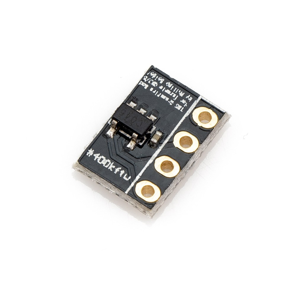
I actually have a C045 single inverter from my TBS Crossfire mod lol; might give it a shot
Railcore II ZL
-
@JohnOCFII said in Inconsistent results with optical encoder wheel filament sensor:
minimum 91%, maximum 109%
awesome

so would be cool if @dc42 can implement sometimes in future Schottky input on the MCU for endstop inputs as it is supported from what I see in the datasheet.
-
Thanks -- my next step is to re-test with the higher resolution encoder wheel. Right now I'm on the "middle" wheel.

-
@fractalengineer said in Inconsistent results with optical encoder wheel filament sensor:
@JohnOCFII brilliant results that is a huge improvement
I actually have a C045 single inverter from my TBS Crossfire mod lol; might give it a shot
Does that have the Schmitt trigger in it?
-
@JohnOCFII ah right, it doesn't.
I've found some in the same package though; might work on making a custom pcb with sensor and trigger included
https://lcsc.com/product-detail/74-Series_ON-Semiconductor-ON-M74VHC1G132DFT1G_C233567.html
-
@fractalengineer said in Inconsistent results with optical encoder wheel filament sensor:
@JohnOCFII ah right, it doesn't.
I've found some in the same package though; might work on making a custom pcb with sensor and trigger included
Cool idea! I was just thinking, "well, it looks like I've got a usable solution -- now how am I going to package up this mess..."
-
@arhi said in Inconsistent results with optical encoder wheel filament sensor:
@JohnOCFII said in Inconsistent results with optical encoder wheel filament sensor:
minimum 91%, maximum 109%
awesome
so would be cool if @dc42 can implement sometimes in future Schottky input on the MCU for endstop inputs as it is supported from what I see in the datasheet.
Yeah, it would be. And based on my testing so far, I wish I had known that the CONN_LCD input apparently does have the same input filter (or something) as the e0 and e1stop. I certainly got less wacky results once I switched from CONN_LCD to e1stop.
-
@JohnOCFII said in Inconsistent results with optical encoder wheel filament sensor:
The LED on the optical sensor now is behaving opposite to the sensor on the DUET e1stop.
Yes, it's inverted, but it makes ZERO difference since you are not using it as an endstop, but rather as a pulse for the filament monitor.
If you care to have the lights be the same, just wire two of the inverters in series and it will invert twice and make it not-inverted anymore!
Pin 1 input from sensor
Pin 2 connect to pin 3
Pin 4 connect to Duet. -
@alankilian said in Inconsistent results with optical encoder wheel filament sensor:
If you care to have the lights be the same, just wire two of the inverters in series and it will invert twice and make it not-inverted anymore!
Pin 1 input from sensor
Pin 2 connect to pin 3
Pin 4 connect to Duet.Oooh! I might try that. Thanks!