• Tags
  • Documentation
  • Order
  • Register
  • Login
Duet3D Logo Duet3D
  • Tags
  • Documentation
  • Order
  • Register
  • Login

ST3Di Modelsmart 280 - Duet Maestro repair/upgrade

Scheduled Pinned Locked Moved
My Duet controlled machine
13
139
9.0k
Loading More Posts
  • Oldest to Newest
  • Newest to Oldest
  • Most Votes
Reply
  • Reply as topic
Log in to reply
This topic has been deleted. Only users with topic management privileges can see it.
  • undefined
    Blacksheep99 @Phaedrux
    last edited by 4 Jan 2021, 18:57

    @Phaedrux said in ST3Di Modelsmart 280 - Duet Maestro repair/upgrade:

    @Blacksheep99 said in ST3Di Modelsmart 280 - Duet Maestro repair/upgrade:

    I am wondering if I am better removing the ribbon and replacing it with a wiring loom. That way at least I know which part connects to where on the board.

    I would think so. But looking at your other thread on the ribbon cable it looks like there is a PCB that should be fairly easy to figure out with a multimeter and some patience.

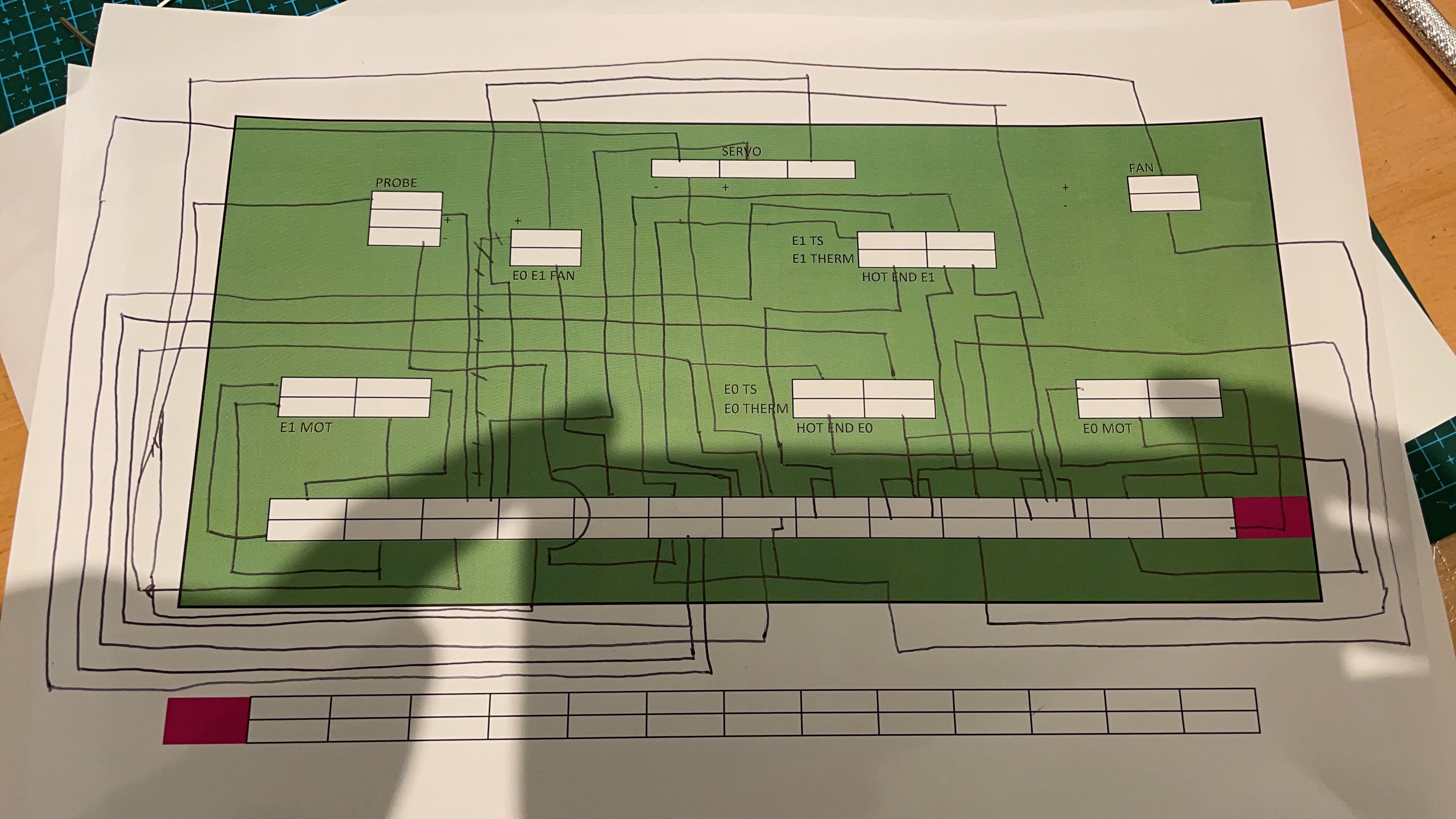
    Thanks for the feedback. I attempted that yesterday. Forgive my rudimentary diagram. I was just trying to trace the pins. I expected a pin to a pin but as you can see that wasn't the case at all. This just adds to my confusion.

    FE823C99-6B3B-4FE4-B431-D8BBA5C6E350.JPG

    1 Reply Last reply Reply Quote 0
    • undefined
      Phaedrux Moderator
      last edited by 4 Jan 2021, 19:05

      Some of the pins may be power or ground and may be shared between several things. Data/signal pins would be unique. This may be a problem if for instance they share a ground pin between fans and heaters which won't work with the Duet since the PWM signal is switched on the negative side.

      Z-Bot CoreXY Build | Thingiverse Profile

      1 Reply Last reply Reply Quote 0
      • undefined
        Blacksheep99
        last edited by 5 Jan 2021, 09:13

        Thanks for the info.

        Any recommendations of where to buy suitable components to create a new loom from the print head? I'm wondering about using the existing connectors or best to remove all that and crimp wires to wires?

        Printer head.jpg

        1 Reply Last reply Reply Quote 0
        • ?
          A Former User
          last edited by A Former User 1 May 2021, 09:49 5 Jan 2021, 09:49

          Its probably more a question of identifying the parts in use than where to buy; could look like molex microfit, so maybe something like https://www.molex.com/molex/products/part-detail/crimp_housings/0430200200 for the loose connector to the top right left.

          however you might spend less time re-crimping it all than to identifying them with 100% certainty when its not a goal in itself to create compatibility. i've had a bias towards making sure my conversion was reversible, but when the original hardware is "nfg" then whatever is easiest might be better option.

          undefined undefined 2 Replies Last reply 5 Jan 2021, 10:04 Reply Quote 0
          • undefined
            Veti @A Former User
            last edited by Veti 1 May 2021, 10:06 5 Jan 2021, 10:04

            @bearer

            not quite. the number on the connector is 43025
            its https://www.molex.com/molex/products/part-detail/crimp_housings/0430250200

            edit: sorry i see you posted the female part

            1 Reply Last reply Reply Quote 0
            • undefined
              Blacksheep99 @A Former User
              last edited by 5 Jan 2021, 12:14

              @bearer I figure that the printer would be either thrown or sold for next to nothing as spares or repair. As such all I'm interested in is getting it functioning again and learning along the way. This is my first foray in to Duet and any form or modifying a printer. It doesn't really owe me anything. Thanks for the pointer with the connectors.

              1 Reply Last reply Reply Quote 0
              • undefined
                Blacksheep99
                last edited by 5 Jan 2021, 12:27

                I'm favouring a rewire so will be researching that. Going this route then I will need to have a separate bed level probe. Any recommendations?

                My plan would be to use the current probe/end stop purely as an end stop.

                end stop.jpg

                1 Reply Last reply Reply Quote 0
                • undefined
                  Veti
                  last edited by 5 Jan 2021, 13:21

                  depends on your surface.

                  there is the dc42 ir probe
                  or a good capacitive sensor.

                  1 Reply Last reply Reply Quote 0
                  • undefined
                    Blacksheep99
                    last edited by 5 Jan 2021, 13:39

                    It's currently a glass bed. Thanks, I'll check out those options.

                    undefined 1 Reply Last reply 5 Jan 2021, 14:03 Reply Quote 0
                    • undefined
                      Veti @Blacksheep99
                      last edited by 5 Jan 2021, 14:03

                      @Blacksheep99
                      glass is not good with either of those.

                      i think with glass your best choice is a bltouch.
                      or the one i prefer https://www.thingiverse.com/thing:3303618

                      1 Reply Last reply Reply Quote 0
                      • undefined
                        Blacksheep99
                        last edited by 5 Jan 2021, 14:08

                        I've just been reading up on the options, came to that conclusion that the glass bed would provide some issues. I'm aware of the BL touch. I'll look at those options, thanks.

                        1 Reply Last reply Reply Quote 0
                        • undefined
                          Blacksheep99
                          last edited by 6 Jan 2021, 11:17

                          I made some progress last night. Having updated the Duet to 3.2 I wanted to create a base config and see if I could get the printer to at least power up. I was able to connect the X,Y & Z motors, plus two end stops (the X end stop is the servo controlled probe. I was able to home Y and Z and control them via the web interface. I then connected the heated bed and ran the autotune. It completed and the bed was holding temp which is good.

                          I don't fully understand the config setup using the webtool, if someone can explain it in simple terms to me that could be helpful.

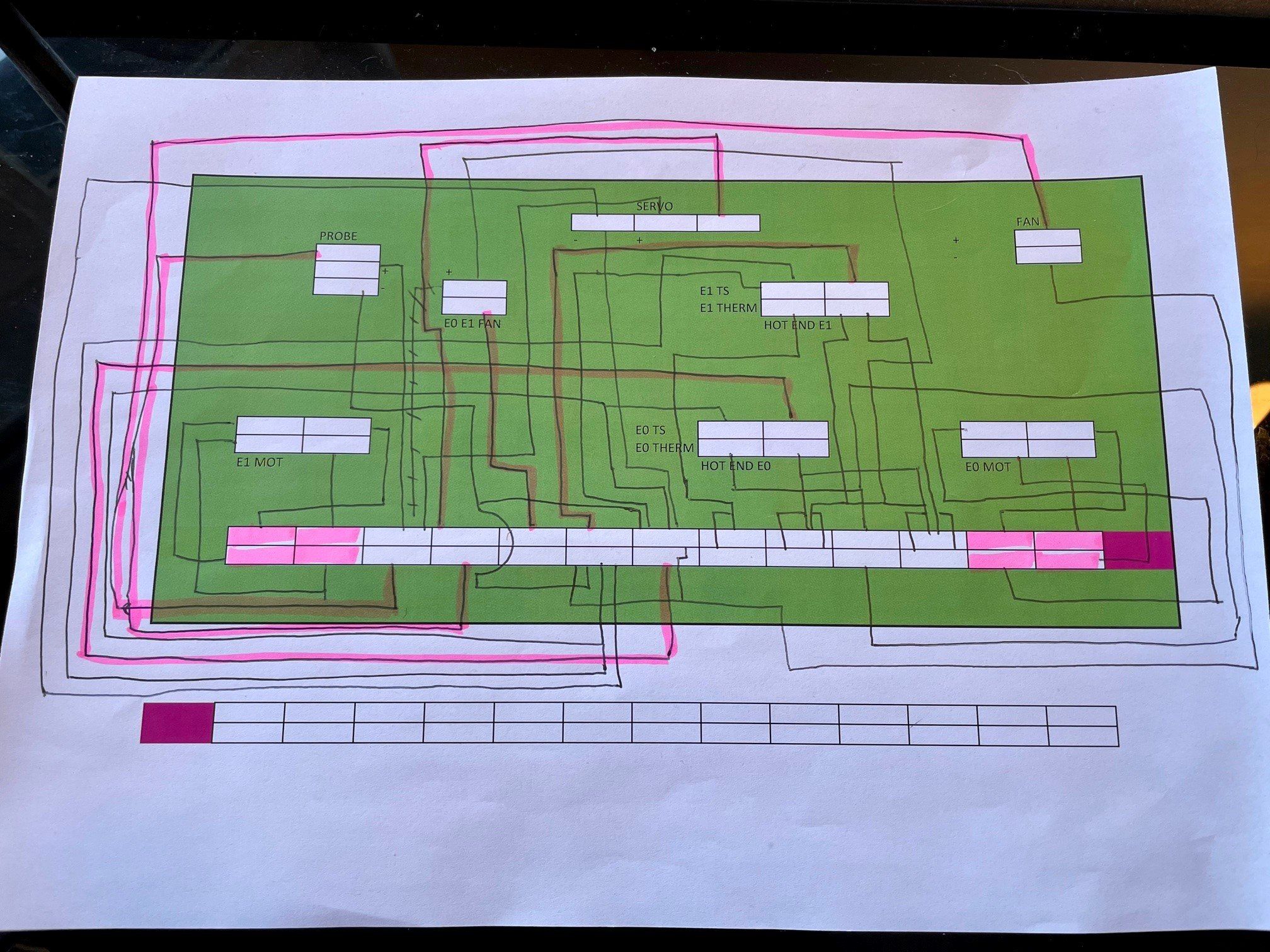
                          So all in all good progress, well I felt happy. I keep avoiding how to connect up the print heads and associated components. Advice on this area would be welcome. What seems easiest is if I can reuse the existing wiring from the components with the ribbon and then connect from the ribbon to the Duet. I have some Dupont cables which can connect to the ribbon. My issue remains how things were connected. It seems multiple components are taking power from the same pins. Using my crude schematic I identified those pins with a single feed and traced it to the respective component. See the highlighted paths.

                          1 Reply Last reply Reply Quote 0
                          • undefined
                            Blacksheep99
                            last edited by 6 Jan 2021, 11:20

                            st3di wiring path.jpg

                            1 Reply Last reply Reply Quote 0
                            • undefined
                              jay_s_uk
                              last edited by 6 Jan 2021, 11:23

                              multiple power from the same pin is fine as all the mosfets switch to ground.

                              Main thing to think about is the total amount of power being drawn of the appropriate output is used.

                              What bits are you confused with with the config tool? It won't be able to cover all setup requirements and is really only used as a base for configuration.

                              Owns various duet boards and is the main wiki maintainer for the Teamgloomy LPC/STM32 port of RRF. Assume I'm running whatever the latest beta/stable build is

                              undefined 1 Reply Last reply 6 Jan 2021, 11:28 Reply Quote 0
                              • undefined
                                Blacksheep99
                                last edited by 6 Jan 2021, 11:26

                                So the motors have a pin to pin mapping. The probe\end stop has one but shared power circuits, the servo has a single feed to one pin with shared power, the hot ends have a single pin but share power also. This seems to make things complicated if I try to map this to the Duet. So I'm thinking I can use the spare wires in the ribbon plus an additional one if required and then wire back to the Duet at the other end. This way all the power circuits are kept seperate..

                                undefined 1 Reply Last reply 6 Jan 2021, 12:07 Reply Quote 0
                                • undefined
                                  Blacksheep99 @jay_s_uk
                                  last edited by 6 Jan 2021, 11:28

                                  @jay_s_uk said in ST3Di Modelsmart 280 - Duet Maestro repair/upgrade:

                                  multiple power from the same pin is fine as all the mosfets switch to ground.

                                  Main thing to think about is the total amount of power being drawn of the appropriate output is used.

                                  What bits are you confused with with the config tool? It won't be able to cover all setup requirements and is really only used as a base for configuration.

                                  Thanks, that's helpful to know. This is the area I do not understand currently....

                                  2021-01-06 11_26_50-RRF Config Tool.jpg

                                  1 Reply Last reply Reply Quote 0
                                  • undefined
                                    jay_s_uk
                                    last edited by 6 Jan 2021, 11:33

                                    what software does the printer originally run?

                                    Owns various duet boards and is the main wiki maintainer for the Teamgloomy LPC/STM32 port of RRF. Assume I'm running whatever the latest beta/stable build is

                                    undefined 1 Reply Last reply 6 Jan 2021, 11:35 Reply Quote 0
                                    • undefined
                                      Veti
                                      last edited by 6 Jan 2021, 11:33

                                      thats the difficult part.

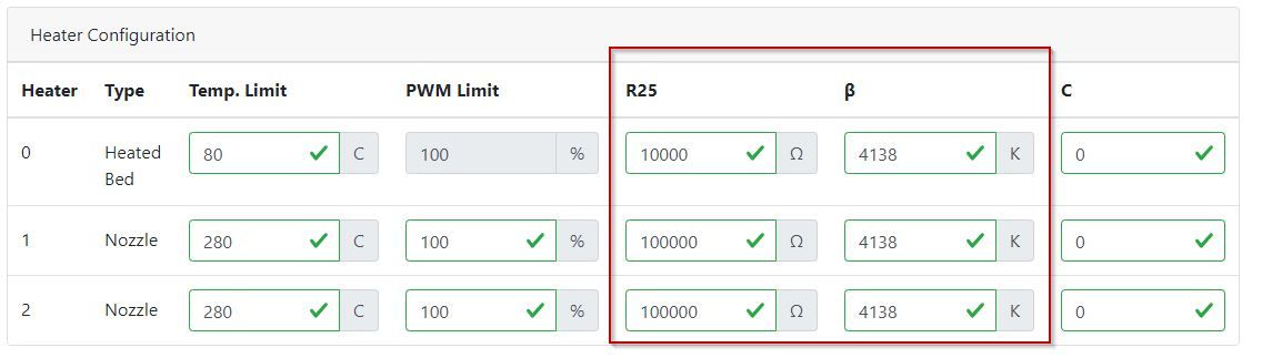
                                      is there any way you can get documentation as to what the exact model number is of the thermistor?

                                      undefined 1 Reply Last reply 6 Jan 2021, 11:37 Reply Quote 0
                                      • undefined
                                        Blacksheep99 @jay_s_uk
                                        last edited by 6 Jan 2021, 11:35

                                        @jay_s_uk said in ST3Di Modelsmart 280 - Duet Maestro repair/upgrade:

                                        what software does the printer originally run?

                                        No idea. I was able to get it working with Cura and outputting gcode based on marlin but that's it. There was no way to access the FW etc.

                                        1 Reply Last reply Reply Quote 0
                                        • undefined
                                          jay_s_uk
                                          last edited by 6 Jan 2021, 11:36

                                          you may have to either take a punt on the thermistors as something like 3950's or 4092's.
                                          Other than that you'll have to change them so you know exactly what you they are.
                                          I've just had a quick google and nothing has come up.

                                          Owns various duet boards and is the main wiki maintainer for the Teamgloomy LPC/STM32 port of RRF. Assume I'm running whatever the latest beta/stable build is

                                          1 Reply Last reply Reply Quote 0
                                          12 out of 139
                                          • First post
                                            12/139
                                            Last post
                                          Unless otherwise noted, all forum content is licensed under CC-BY-SA